Connector

a technology of connecting rods and connectors, which is applied in the direction of coupling contact members, coupling device connections, coupling bases/cases, etc., can solve the problems of insufficient effect in suppressing the transfer of vibration and the wire to the terminal fittings can be impacted, so as to suppress the transfer of vibration, simplify the shape of the housing body, and reduce the effect of vibration

Active Publication Date: 2017-08-03
SUMITOMO WIRING SYST LTD
View PDF0 Cites 6 Cited by
  • Summary
  • Abstract
  • Description
  • Claims
  • Application Information

AI Technical Summary

Benefits of technology

[0008]The inner housing and the outer housing may be positioned via at least one resilient positioning member. Thus, vibration energy transferred from the wire to the outer housing is attenuated by the resilient positioning member, thereby suppressing the transfer of vibration to the inner housing.
[0009]The inner housing may be connectable to a mating housing that has a mating terminal. The inner housing may be formed with at least one displacement restricting portion configured to restrict a relative displacement with respect to the mating housing. According to this configuration, the inner housing is connected to the mating housing with a relative displacement restricted and relative displacements of the terminal fitting and the mating terminal are restricted. Thus, fine sliding abrasion between the terminal fitting and the mating terminal can be suppressed.
[0010]The inner housing may include a housing body configured to accommodate the terminal fitting. A front retainer may be mounted in a front end part of the housing body and may be configured to restrict the escape of the terminal fitting from the housing body. The displacement restricting portion may project on an outer peripheral surface of the front retainer and may be capable of being held in close contact with an inner periphery of a receptacle of the mating housing while being plastically deformed. According to this configuration, the front retainer is formed with the displacement restricting portion. Thus, the shape of the housing body can be simplified.
[0011]The connector may further include at least one locking lance configured to retain the terminal fitting inserted into the inner housing from behind. A restricting projection may be formed on a front wall of the front retainer and may be configured to restrict a movement of the terminal fitting by coming into contact with a front surface of the terminal fitting. Thus, the terminal fitting is sandwiched between the locking lance and the restricting projection substantially in a front-back direction. According to this configuration, a movement of the terminal fitting in the front-back direction can be restricted reliably, utilizing the front retainer separate from the housing body. In this way, fine sliding abrasion between the terminal fitting and the mating terminal can be reliably prevented.
[0012]The inner housing may be connectable to a mating housing including at least one mating terminal, and the inner housing may be formed with a lock arm configured to hold a connected state to the mating housing by being locked to the mating housing. According to this configuration, the inner housing and the mating housing are locked in the connected state by the lock arm. Thus, fine sliding abrasion between the terminal fitting and the mating terminal can be suppressed.
[0015]Since vibration energy of the wire is transferred to the outer housing via the vibration damping ring and attenuated by an inertial force of the outer housing, the transfer of vibration to the terminal fitting is suppressed. No vibration transfer path by direct contact between the vibration damping ring and the inner housing is present between the vibration damping ring and the terminal fitting, a function of suppressing the transfer of vibration from the wire to the terminal fitting is excellent.

Problems solved by technology

Thus, the transfer of vibration of the wire to the terminal fitting via the resilient portion and the terminal-side housing carrier is unavoidable and a sufficient effect cannot be expected in suppressing the transfer of vibration to the terminal fitting.

Method used


Image

  • Connector
  • Connector
  • Connector

Examples


Embodiment Construction

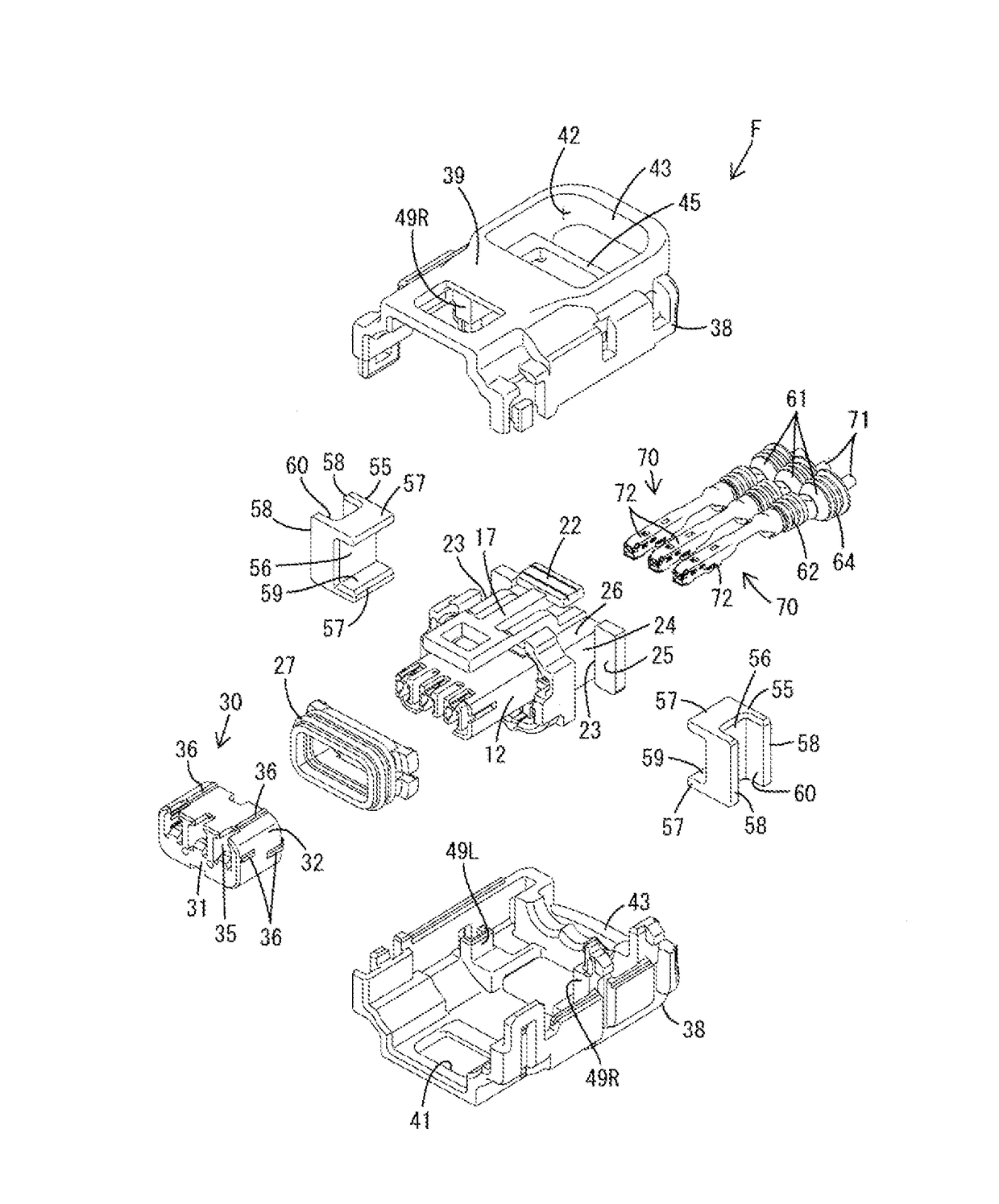
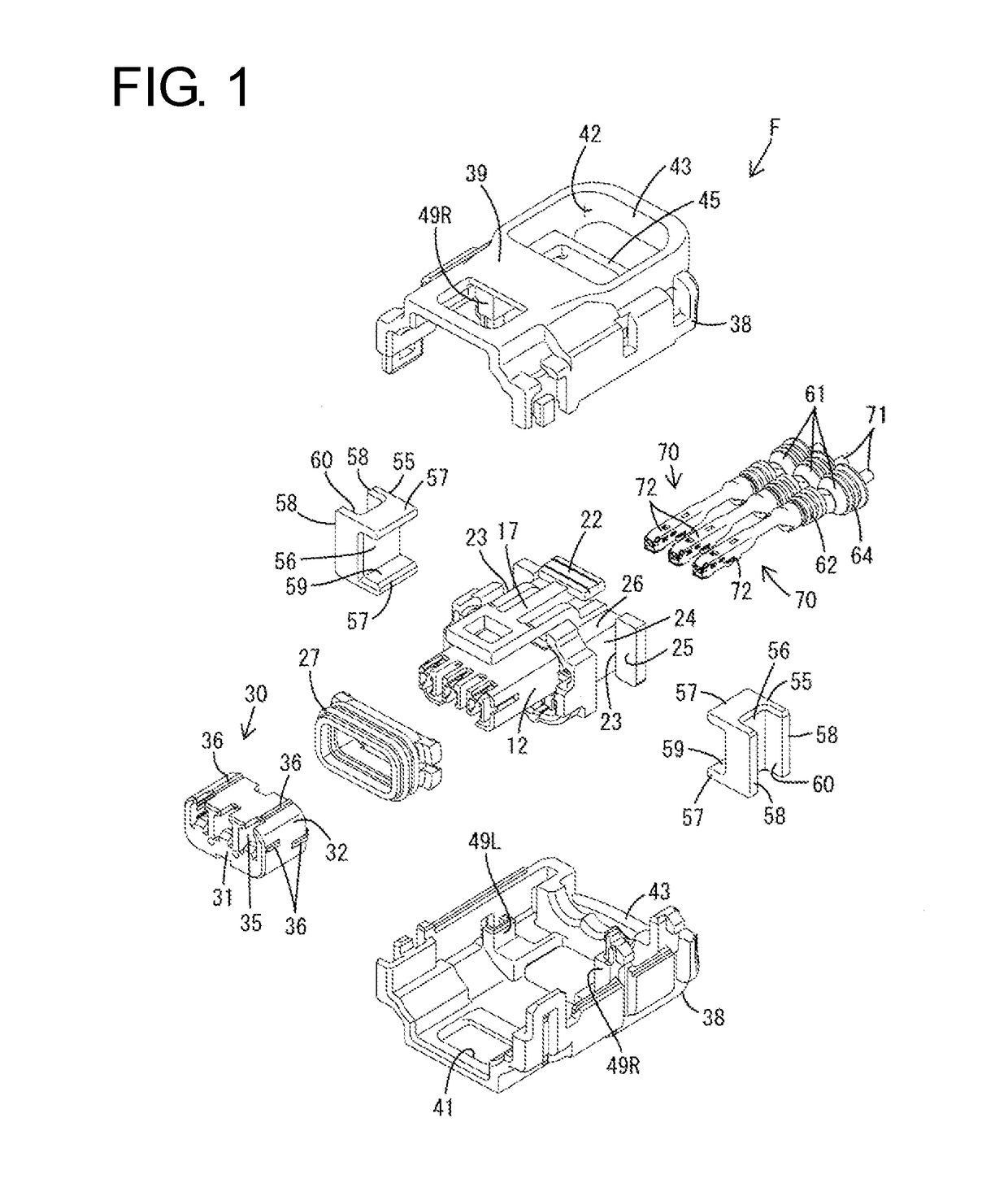
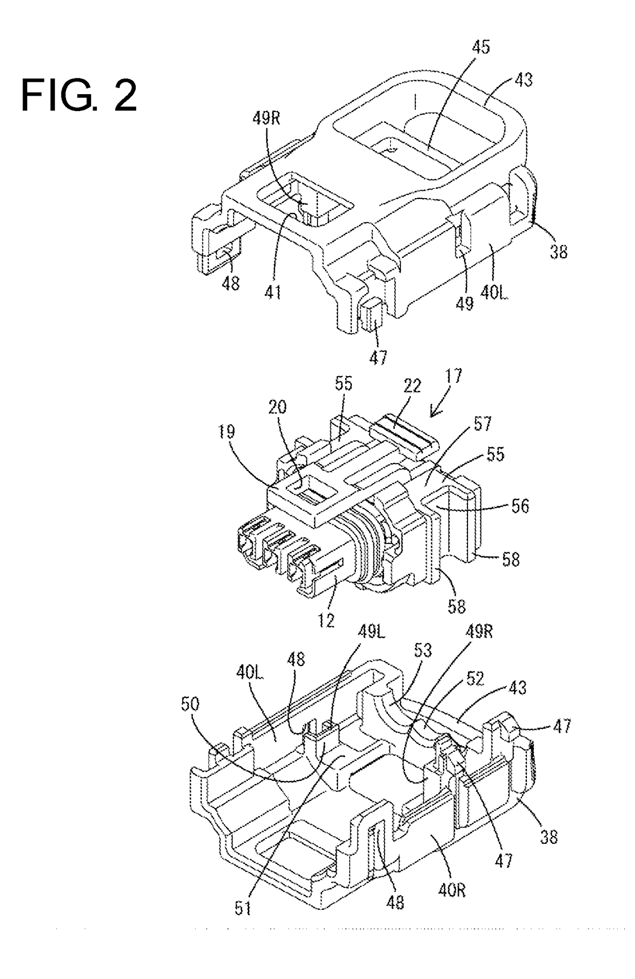
[0038]One specific embodiment of the invention is described with reference to FIGS. 1 to 21. Note that, in the following description, a left side in FIGS. 7, 9 to 12, 15 and 19, an oblique left lower side in FIGS. 1 to 4 and 21 and an oblique right upper side in FIGS. 8, 16 and 17 are defined as a front side concerning a front-back direction. Concerning a vertical direction, upper and lower sides shown in FIGS. 1 to 6, 8 to 10, 13 to 18, 20 and 21 are defined as upper and lower sides. A connector of this embodiment includes a male connector M and a female connector F connectable to and separable from each other.

[0039]As shown in FIGS. 9 and 10, the male connector M has a male housing 80 made e.g. of synthetic resin. The male housing 80 includes a terminal holding portion 81 and a receptacle 82 projecting in the same direction as a connecting direction to the female connector F (right in FIGS. 9 and 10) from the terminal holding portion 81. A lock projection 83 is formed on the upper...


PUM


Abstract

A connector (F) includes an inner housing (11). Terminal fittings (72) are fixed to front end parts of wires (71) and are inserted into the inner housing (11) from behind. An outer housing (37) is held out of contact with the terminal fittings (72) and is mounted relatively displaceably with respect to the inner housing (11). Vibration damping rings (64) are fit externally on the wires (71) in a state out of contact with the inner housing (11), and are held resiliently in contact with the outer housing (37).

Description

BACKGROUND[0001]1. Field of the Invention[0002]The invention relates to a connector.[0003]2. Related Art[0004]Japanese Unexamined Patent Publication No. 2015-018617 discloses a connector in which a terminal-side housing carrier for accommodating and holding terminal fittings and a wire-side housing carrier for accommodating wires are coupled via a resilient portion. In this connector, if the wire vibrates, the terminal-side housing carrier and the wire-side housing carrier are displaced relatively while resiliently deforming the resilient portion and the vibration of the wire can be attenuated by this resilient deformation of the resilient portion.[0005]In the above-described connector, the wires are directly in contact with the resilient portion and the resilient portion is directly in contact with the terminal-side housing carrier. Thus, the transfer of vibration of the wire to the terminal fitting via the resilient portion and the terminal-side housing carrier is unavoidable and ...

Claims


Application Information

Patent Timeline
Patent Type & Authority Applications(United States)
IPC IPC(8): H01R13/533H01R13/629H01R13/432H01R13/426H01R13/52H01R13/14
CPCH01R13/533H01R13/5208H01R13/62955H01R13/432H01R13/426H01R13/14H01R13/502H01R13/5833H01R13/4223H01R13/4364H01R13/506H01R13/5205H01R13/6272
Inventor HASHIMOTO, YOUJIROUNAKAI, KAZUO
Owner SUMITOMO WIRING SYST LTD
Why Eureka
Try Eureka