Method for detecting an operating state of an inkjet print head nozzle

Active Publication Date: 2017-08-10
OCE TECH
View PDF4 Cites 6 Cited by
  • Summary
  • Abstract
  • Description
  • Claims
  • Application Information

AI Technical Summary

Benefits of technology

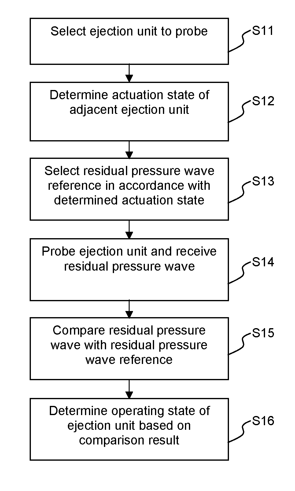
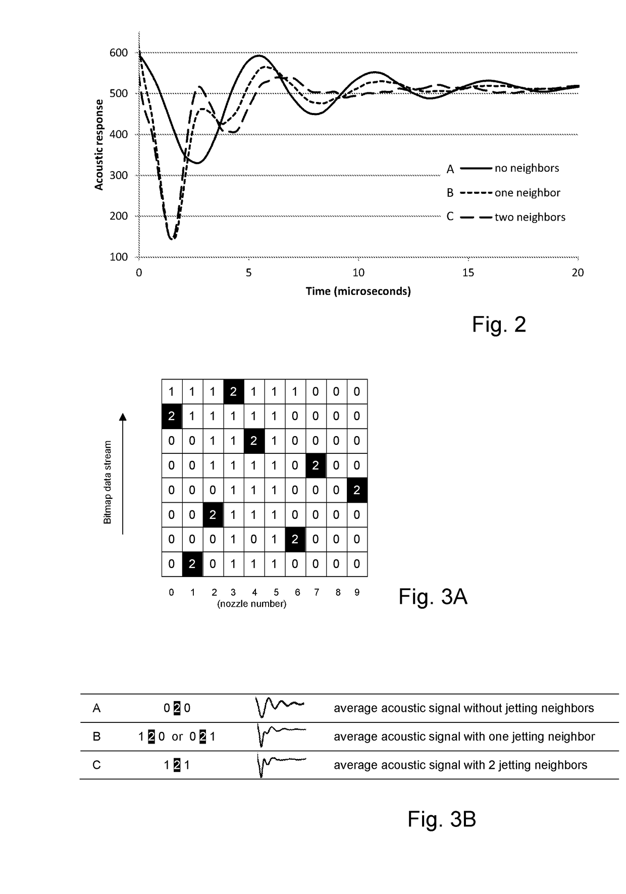
[0020]The method according to the present invention allows performing the operating state detection also when the print head is printing. For example, in an embodiment, the method may be performed while an image is printed by image-wise ejection of droplets from the inkjet print head, wherein step c) comprises determining the presence of a pressure wave in the second ejection unit based on print data, the print data indicating when an ejection unit is to eject a droplet. Commonly, print data is supplied to a print head indicating which ejection unit needs to expel a droplet and when. Thus, while print head and recording medium, e.g. paper, are controlled to move relative to each other, droplets are expelled with such a timing that the droplets land on the recording medium at a desired position. Thus, an image may be formed on the recording medium.
[0021]Detecting an operating state of an ejection unit may

Problems solved by technology

In particular, one of the residual pressure wave references in the set may correspond to the operation condition wherein the second ejection un

Method used


Image

  • Method for detecting an operating state of an inkjet print head nozzle
  • Method for detecting an operating state of an inkjet print head nozzle
  • Method for detecting an operating state of an inkjet print head nozzle

Examples


Example

DETAILED DESCRIPTION OF THE DRAWINGS

[0036]The present invention will now be described with reference to the accompanying drawings, wherein the same reference numerals have been used to identify the same or similar elements throughout the several views.

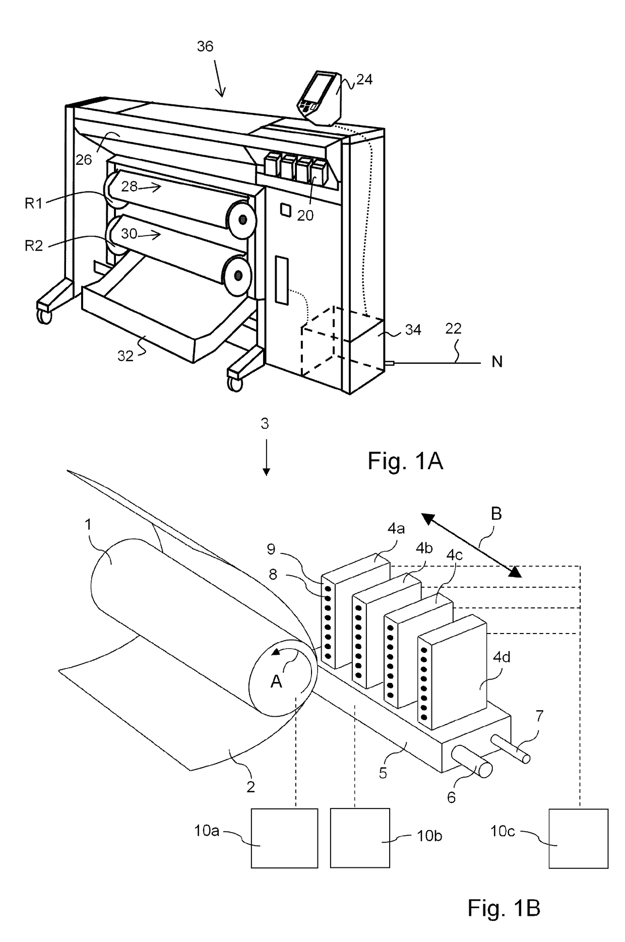
[0037]FIG. 1A shows an image forming apparatus 36, wherein printing is achieved using a wide format inkjet printer. The wide-format image forming apparatus 36 comprises a housing 26, wherein the printing assembly, for example the ink jet printing assembly shown in FIG. 1B is placed. The image forming apparatus 36 also comprises a storage means for storing image receiving member 28, 30, a delivery station to collect the image receiving member 28, 30 after printing and storage means for marking material 20. In FIG. 1A, the delivery station is embodied as a delivery tray 32. Optionally, the delivery station may comprise processing means for processing the image receiving member 28, 30 after printing, e.g. a folder or a puncher. The wide-f...


PUM


Abstract

For assessing the functioning of an ejection unit of an inkjet print head, a comparison of a residual pressure wave with a residual pressure wave reference is employed. To enable assessment during printing, multiple residual pressure wave references are provided, each relating to a condition relevant to the residual pressure wave. Such a condition may relate to an actuation status of an adjacent ejection unit which may cause crosstalk, for example. When performing the assessment, the condition during assessment is taken into account, for example for selecting a suitable residual pressure wave reference, such that an appropriate and correct assessment can be performed independent from the conditions during assessment.

Description

FIELD OF THE INVENTION[0001]The present invention generally pertains to a method for controlling an inkjet print head in order to detect an operating state of an ejection unit having a nozzle.BACKGROUND ART[0002]A piezo actuated inkjet print head is well known in the art. Such an inkjet print head is commonly provided with a number of ejection units. Each of such ejection units comprises a pressure chamber and a fluidly connected nozzle. The pressure chamber may be filled with a liquid such as an ink and a droplet of the liquid may be expelled through the nozzle by application of a suitable pressure wave in the liquid in the pressure chamber by actuating a piezo actuator that is operatively coupled to the pressure chamber for generating such a pressure wave.[0003]It is also known in the art that the ejection units are sensitive and may become malfunctioning due to a gas bubble, commonly an air bubble, entrapped in the nozzle or pressure chamber. Similarly, dirt or debris may enter t...

Claims


Application Information

Patent Timeline
IPC IPC(8): B41J2/045
CPCB41J2/04581B41J2/0451B41J2/16579B41J2/325B41J2/355B41J2002/14354B41J2/2142
Inventor VEENSTRA, HYLKEMIHAILOVIC, MARKOVENNER, CORNELIS W.M.KHALATE, AMOL A.HUMMEL, TJERK E.C.
Owner OCE TECH
Why Eureka
Try Eureka