Electric diagnostic tape measure and method

a tape measure and tape technology, applied in the field of peripheral nerve nerve devices for measuring nerve conduction, can solve the problems of inaccurate readings and time-consuming, and achieve the effect of determining the distance quickly and easily

Active Publication Date: 2009-07-07
ODDERSON IB R
View PDF9 Cites 23 Cited by
  • Summary
  • Abstract
  • Description
  • Claims
  • Application Information

AI Technical Summary

Benefits of technology

[0007]It is an object of the present invention to provide an electrical diagnostic tape measure that enables a physician to

Problems solved by technology

The act of measuring and marking several sets of reference points on the forearm and hand is very time consuming.
Also, because the set

Method used


Image

  • Electric diagnostic tape measure and method
  • Electric diagnostic tape measure and method
  • Electric diagnostic tape measure and method

Examples


first embodiment

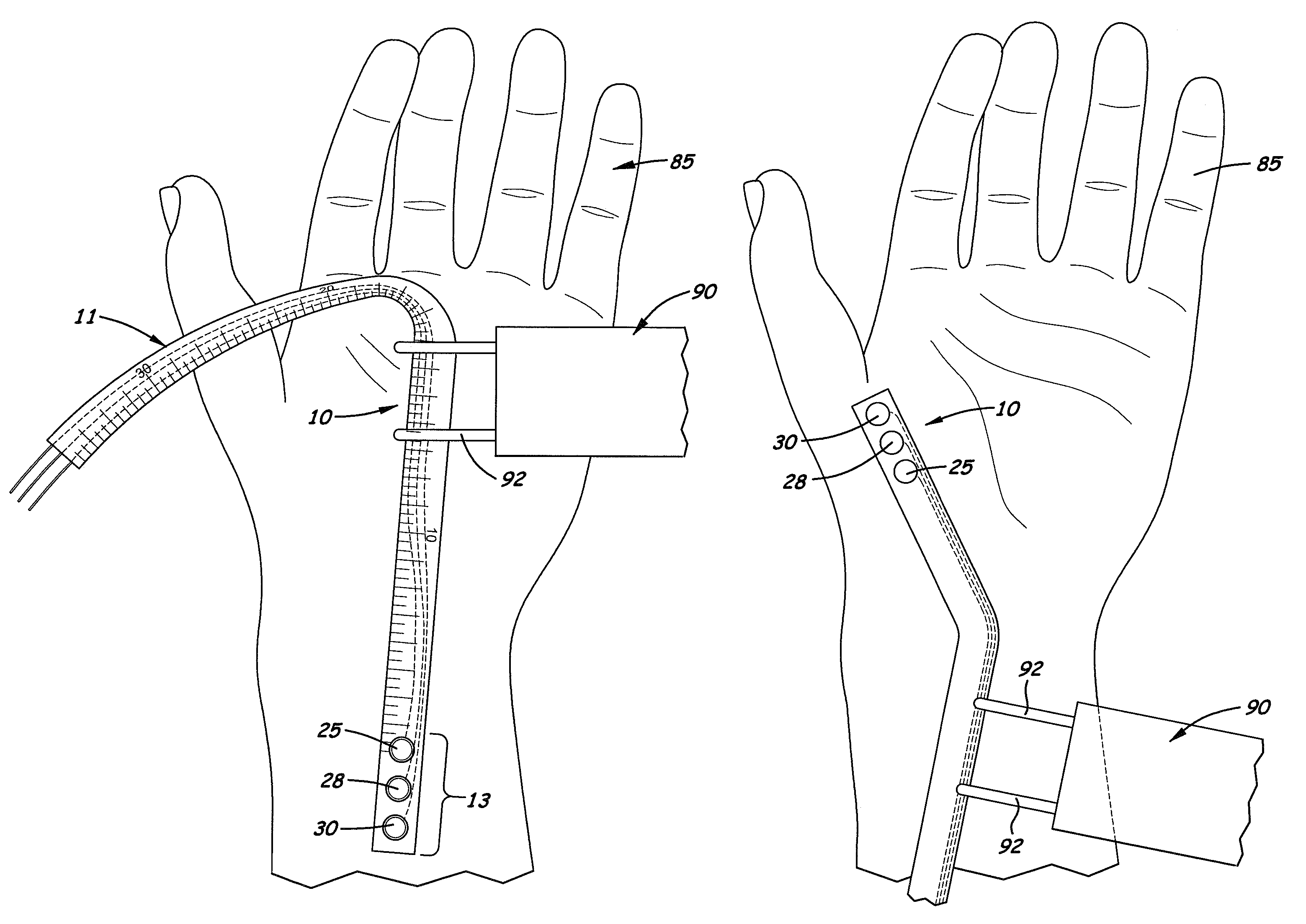
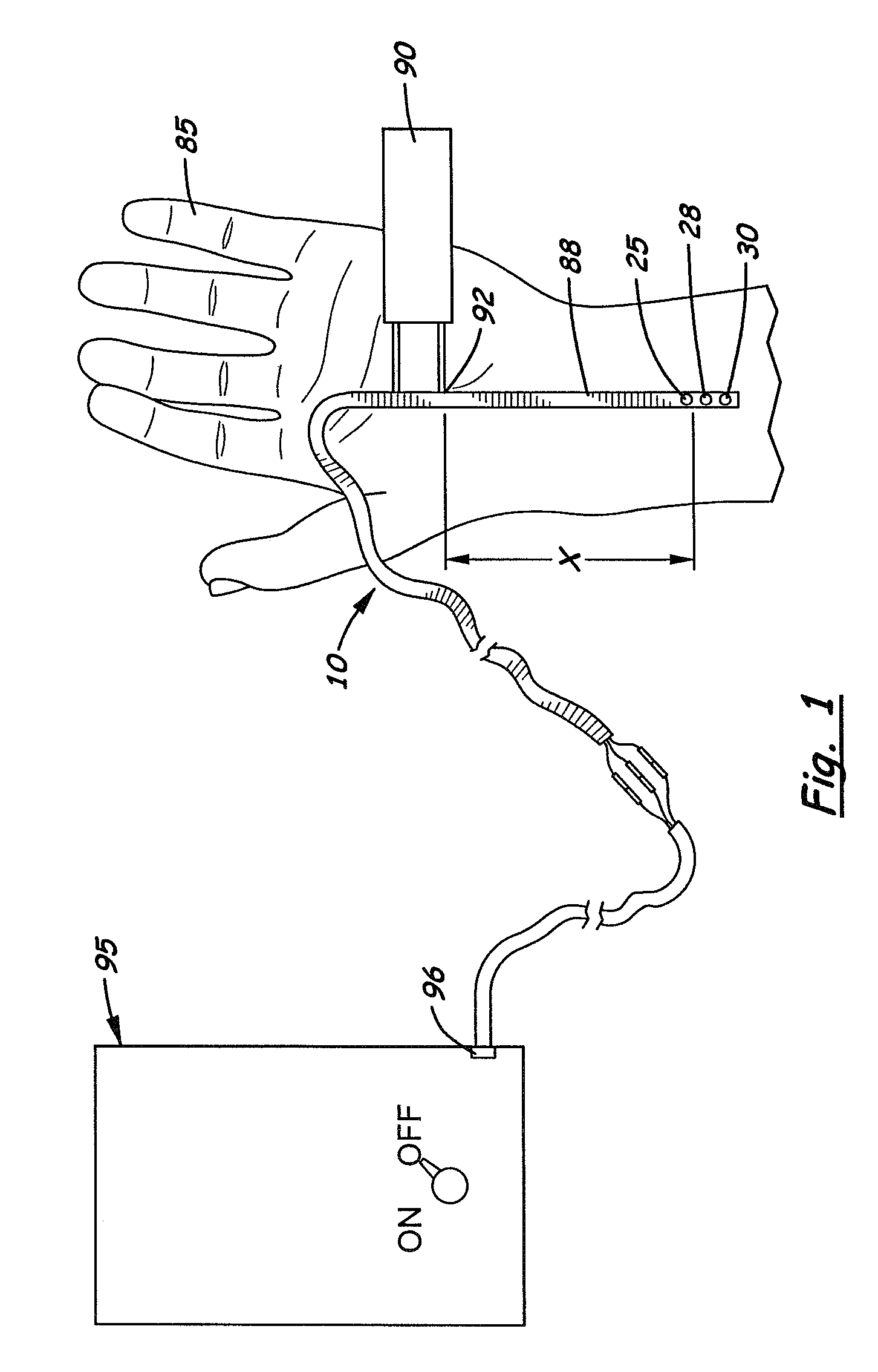
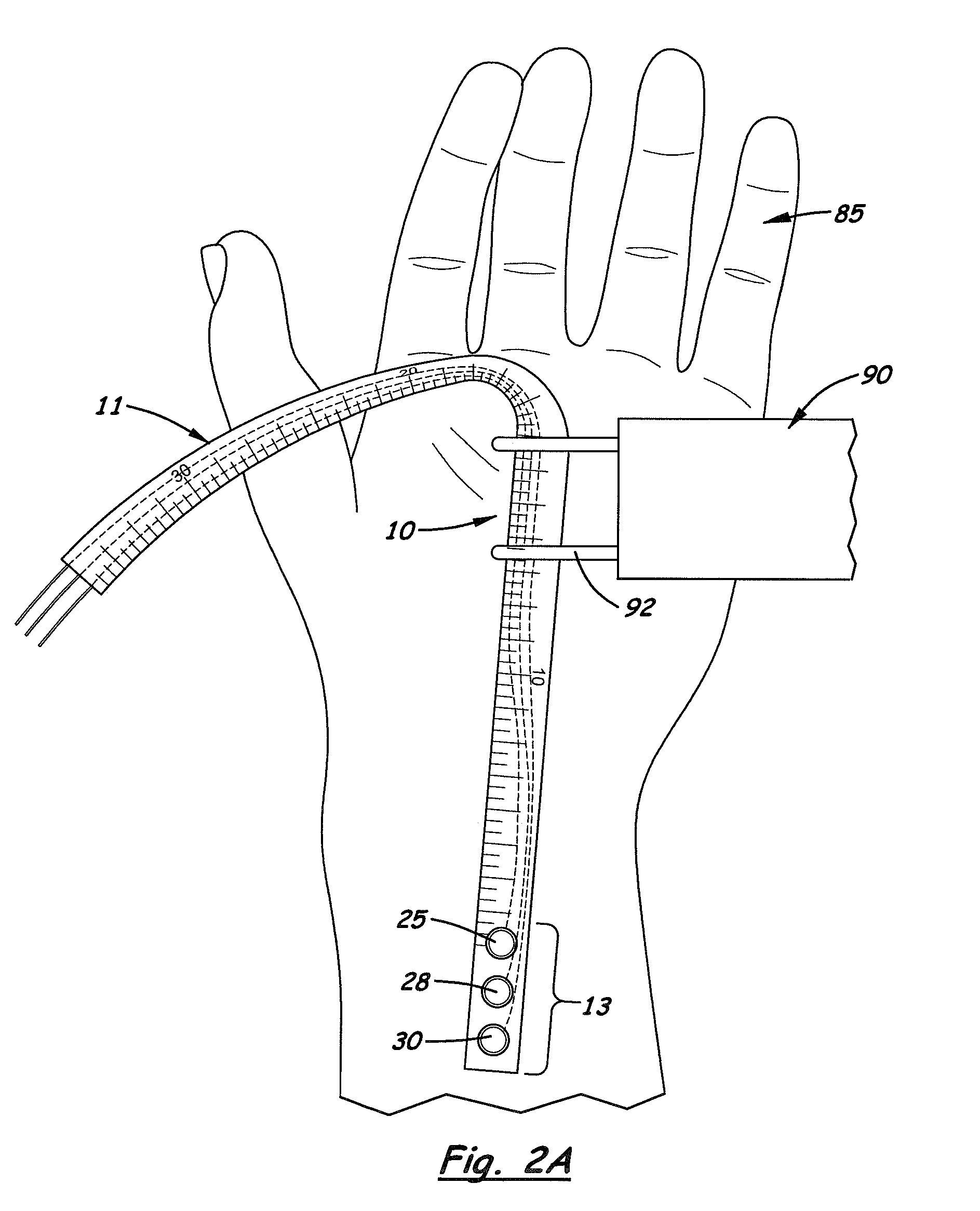
[0028]FIGS. 1, 2A, 2B and 3A show a first embodiment on the invention in which the active recording electrode 25, a reference electrode 28 and a ground electrode 30 all longitudinally aligned and attached to the distal end 13 of the elongated body 11.

[0029]FIG. 3B is a perspective view showing the active recording electrode 25 permanently attached to the elongated body 11 and the reference and ground electrodes 28, 30, respectively being removably attached to the distal end 13 of the elongated body 11.

third embodiment

[0030]FIG. 3C shows the invention in which the active and reference electrodes 25, 28, respectively, are longitudinally aligned and securely attached to the distal end 13 of the elongated body 11. The ground electrode 30 is a separate structure capable of being placed at any desired position on the skin.

fourth embodiment

[0031]FIG. 3D shows the invention in which the reference electrode 28, the ground electrode 30, and wires connecting 36, 38, respectfully, are separate structures from the elongated body 11 and only the active recording electrode 25 is attached at the distal end 13 of the elongated body 11. With this embodiment, the physician is able to adjust the position of the reference and ground electrodes 28, 30 with respect to the active recording electrode 25.


PUM


Abstract

An electric diagnostic tape measure used to measure the electrical conduction of a peripheral nerve using a standard electrical nerve stimulator. The tape measure includes a flexible, elongated body with an active recording electrode mounted or attached to its distal end. Formed on the lower surface of the active recording electrode is a conductive, adhesive layer that temporarily holds the electrode on the patient's skin during a test. Located on the top surface of the elongated body is a distance-measuring index. During a test, the elongated body is aligned so that the end of the distance-measuring index is aligned and registered with the active recording electrode. By moving the nerve stimulator to different locations adjacent to the skin adjacent to the elongated body, the distance of the nerve being tested may be measured. In one embodiment, a wire extends through the elongated body.

Description

[0001]This is a utility patent application which claims benefit of U.S. provisional application No. 60 / 686,331 filed on Jun. 1, 2005.BACKGROUND OF THE INVENTION[0002]1. Field of the Invention[0003]This invention relates to devices for measuring nerve conduction in peripheral nerves and more particularly, to such devices that measure the conduction time and amplitude of a test signal applied to a peripheral nerve.[0004]2. Description of the Related Art[0005]It is common practice in medicine to measure the electrical conduction on a peripheral nerve. A common use of this test is diagnosing carpel tunnel syndrome when electrical conduction in the median nerve is measured across the wrist. During the test, the physician measures the conduction time and the amplitude (compound muscle action potential or sensory nerve action potential) of the nerve by stimulating the nerve with a nerve stimulator. When setting up for the test, the active recording electrode and a second electrode, called ...

Claims


Application Information

Patent Timeline
IPC IPC(8): A61B5/0492A61B5/053A61B5/296
CPCA61B5/04001A61B5/061A61B5/053A61B5/24
Inventor ODDERSON, IB R.
Owner ODDERSON IB R
Why Eureka
Try Eureka