Retrofit reinforcing structure addition and method for wind turbine concrete gravity spread foundations and the like

a technology of gravity spread foundation and retrofitting structure, which is applied in the field of foundations, can solve problems such as foundation collapse, and achieve the effect of efficient installation

Active Publication Date: 2017-08-17
TERRACON CONSULTANTS INC
View PDF15 Cites 12 Cited by
  • Summary
  • Abstract
  • Description
  • Claims
  • Application Information

AI Technical Summary

Benefits of technology

[0008]Accordingly, it is an object of the present invention to provide a retrofit spread foundation reinforcing structure addition and method that restores the integrity of existing gravity spread foundations and extends the useful life thereof for many additional years.
[0013]Another object of the present invention is to provide a retrofit spread foundation reinforcing structure addition in accordance with the preceding objects that, when installed on an existing gravity spread foundation, places the retrofit portion of the foundation under high unit compression loading through tightening of the anchor bolts so as to exceed the maximum internal tension expected from overturning forces of the wind turbine structure on the foundation.
[0014]Yet another object of the present invention is to provide a retrofit spread foundation reinforcing structure addition in accordance with the preceding objects that may be efficiently installed in support of gravity spread foundations of various configurations.

Problems solved by technology

As a result, these gravity spread foundations are susceptible to long term fatigue failures which can result in collapse of the foundation.

Method used


Image

  • Retrofit reinforcing structure addition and method for wind turbine concrete gravity spread foundations and the like
  • Retrofit reinforcing structure addition and method for wind turbine concrete gravity spread foundations and the like
  • Retrofit reinforcing structure addition and method for wind turbine concrete gravity spread foundations and the like

Examples


Embodiment Construction

[0033]Although only one preferred embodiment of the invention is explained in detail, it is to be understood that the embodiment is given by way of illustration only. It is not intended that the invention be limited in its scope to the details of construction and arrangement of components set forth in the following description or illustrated in the drawings. Also, in describing the preferred embodiments, specific terminology will be resorted to for the sake of clarity. It is to be understood that each specific term includes all technical equivalents which operate in a similar manner to accomplish a similar purpose.

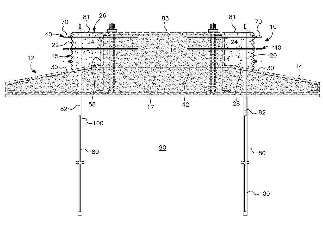
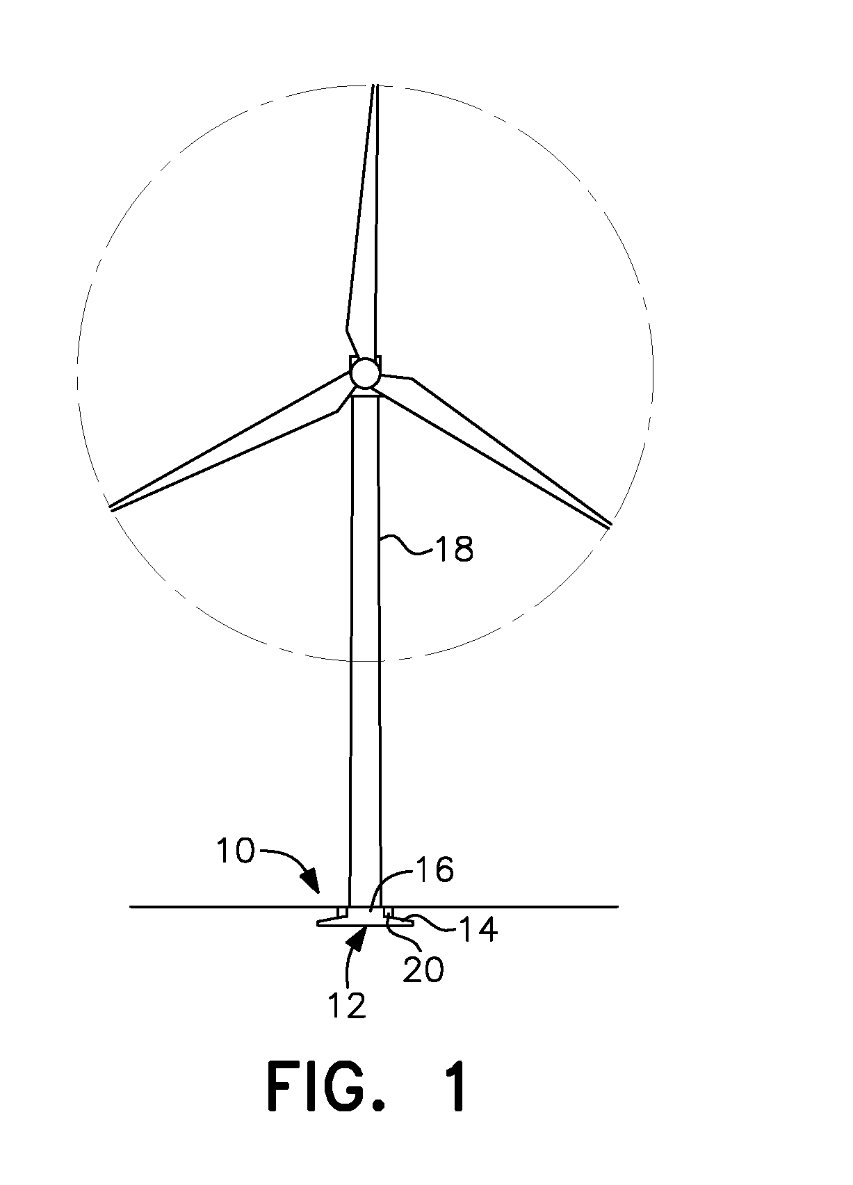
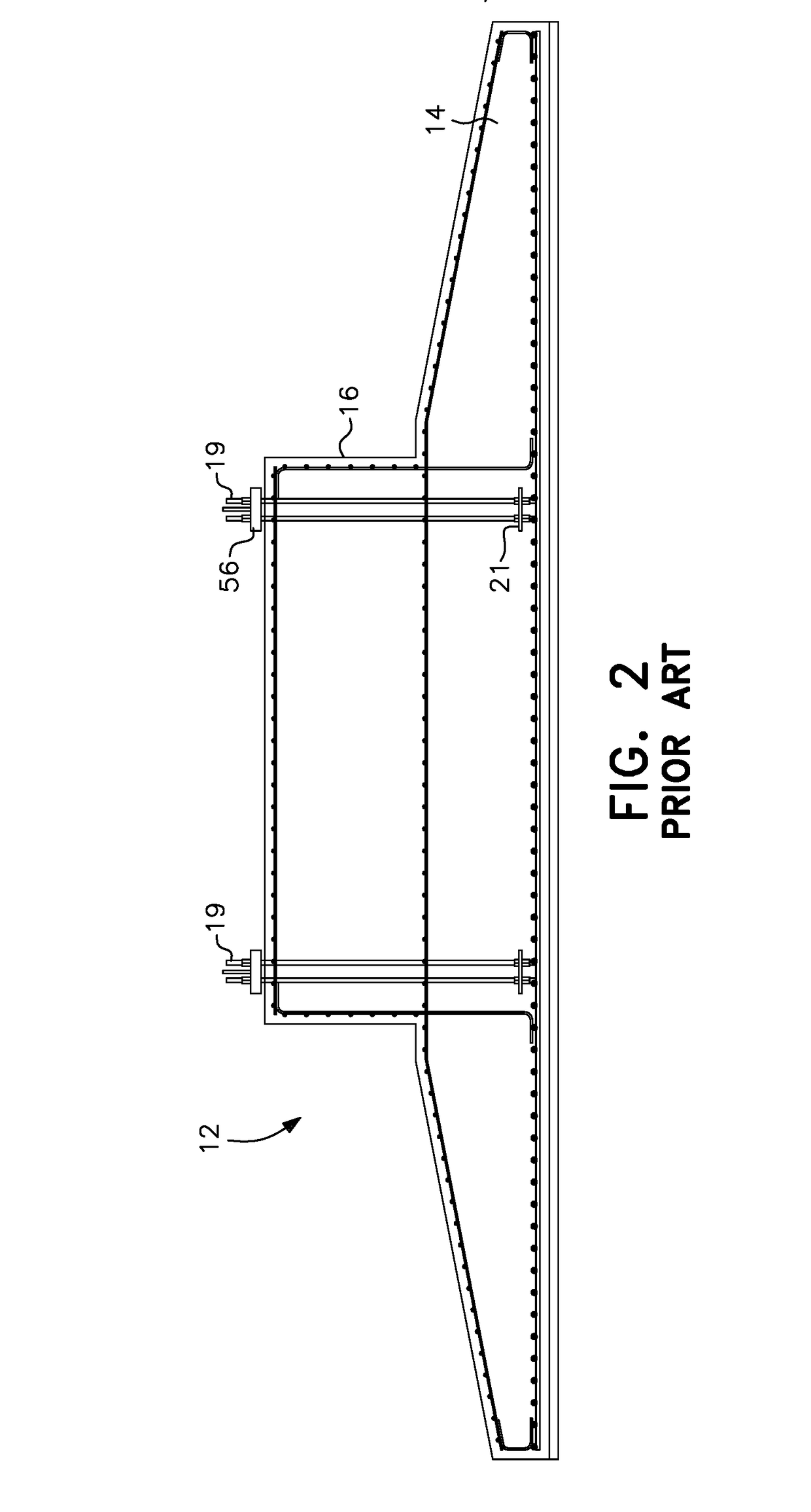
[0034]As shown in FIG. 1, the present invention is directed to a foundation collar reinforcing structure addition, generally designated by reference numeral10, for a conventional existing gravity spread foundation generally designated by reference numeral 12. The gravity spread foundation 12 includes an expanded base or horizontal spread section 14 and a central pedestal 1...


PUM


Abstract

A retrofit reinforcing structure addition and method for an existing gravity spread foundation for a wind turbine or the like haying a central pedestal and a spread section is provided. The retrofit structure addition includes a collar formed around the pedestal of the spread foundation. The collar is formed by a shape sustaining member, such as a CMP, placed around the pedestal to define an annular ring between the CMP and the pedestal that is filled with cementitious material. Radial bolts extend horizontally through the collar and into the side of the pedestal. Soil and / or rock anchor bolts extend vertically through the collar, the spread portion of the foundation and into the underlying soil and / or rock substrate. The radial and anchor bolts are post-tensioned to ensure that the cementitious material of the collar remains in compression and the bolts are always in static tension, strengthening the original gravity spread foundation and extending the fatigue life thereof.

Description

[0001]This application is a divisional of co-pending U.S. application, Ser. No. 14 / 870,955 filed Sep. 30, 2015, which claimed priority from U.S. provisional application, Ser. No. 62 / 060,743 filed Oct. 7, 2014, and also claims the priority of U.S. provisional application, Ser. No. 62 / 211,158 filed Aug. 28, 2015, and hereby claims the priority thereof to which it is entitled.BACKGROUND OF THE INVENTION[0002]Field of the Invention[0003]The present invention is related to the field of foundations for the support of tall, heavy and / or large towers and, more particularly, to a retrofit structure addition and method for reinforcing existing concrete gravity spread foundations currently used to support wind turbines and similar structures, especially those foundations which have failed or are failing due to long term dynamic fatigue.[0004]Description of the Related Art[0005]Concrete gravity spread foundations are often used to support turbines in the 1.5 megawatt (MW) range of which there a...

Claims


Application Information

Patent Timeline
Patent Type & Authority Applications(United States)
IPC IPC(8): E02D27/42E02D5/80E02D37/00E02D27/08
CPCE02D27/425E02D27/08E02D5/80E02D2600/30E02D2300/00E02D2250/0023E02D2200/12E02D37/00F03D13/22E04C5/12E02D27/42F05B2230/80Y02P70/50Y02E10/72Y02E10/728
Inventor HENDERSON, ALLAN P.
Owner TERRACON CONSULTANTS INC
Why Eureka
Try Eureka