Guide Apparatus for a Turbocharger Including a Vane Lever Integrated Adjustment Ring Axial Travel Stop

Inactive Publication Date: 2017-08-17
BORG WARNER INC
View PDF1 Cites 8 Cited by
  • Summary
  • Abstract
  • Description
  • Claims
  • Application Information

AI Technical Summary

Benefits of technology

This patent describes a guide apparatus for a turbocharger which includes a lower vane ring offset axially from an upper vane ring, and a plurality of vanes pivotally coupled between the upper and lower vane rings. An adjustment ring is in mechanical association with the vanes and includes a plurality of apertures, and a vane lever is coupled to each vane and received by the adjustment ring. The vane lever includes a protuberance that faces the adjustment ring to limit axial movement. This facilitates the accurate and efficient control of the turbocharger.

Problems solved by technology

While effective, the interface between the adjustment ring and such stationary axial stops may experience undesired wear as the adjustment ring may operationally rotate against the stationary axial stops.
While effective, the unison ring may be in continuous engagement with the cylindrical pin and the cap during operational rotation of the unison ring causing frictional wear at the contact area of these components.

Method used


Image

  • Guide Apparatus for a Turbocharger Including a Vane Lever Integrated Adjustment Ring Axial Travel Stop
  • Guide Apparatus for a Turbocharger Including a Vane Lever Integrated Adjustment Ring Axial Travel Stop
  • Guide Apparatus for a Turbocharger Including a Vane Lever Integrated Adjustment Ring Axial Travel Stop

Examples


Embodiment Construction

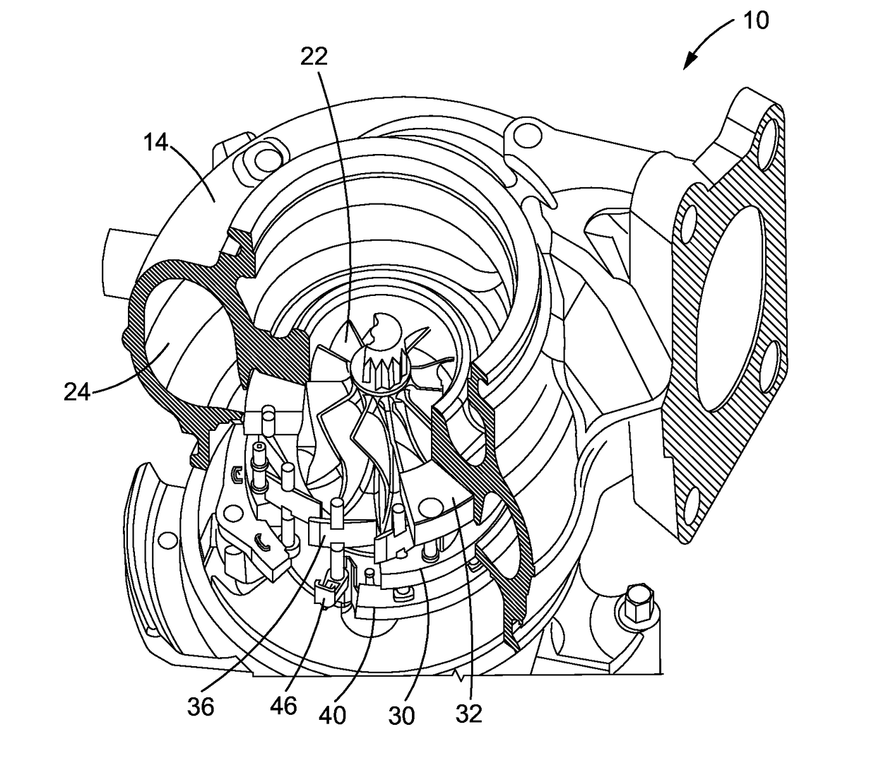
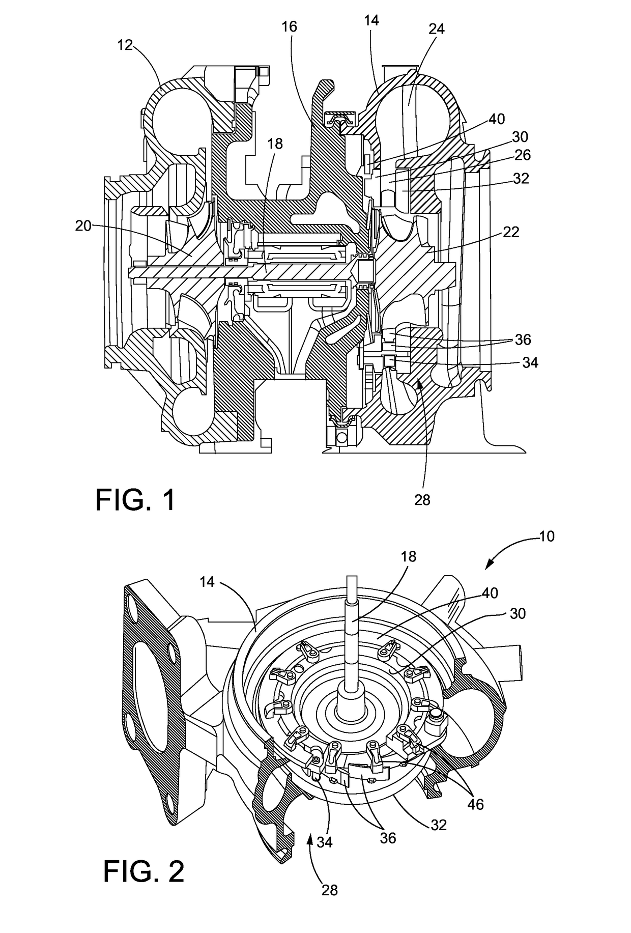
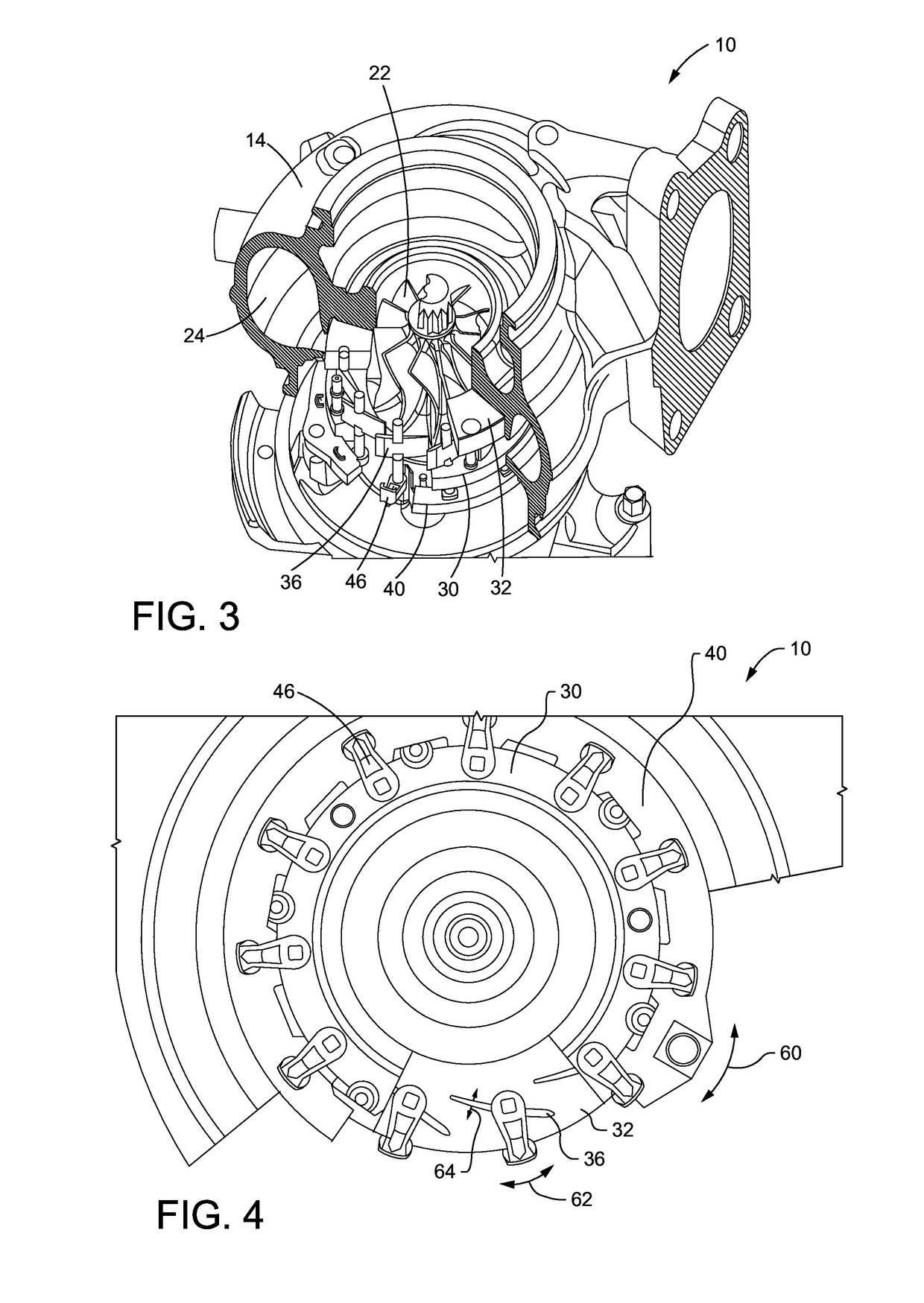
[0017]Referring now to FIG. 1, an exemplary turbocharger constructed in accordance with the present disclosure is generally referred to by reference numeral 10. The turbocharger 10 may be utilized in conjunction with an internal combustion engine of a turbo machine such as, but not limited to, an automobile, a truck, an aircraft, a locomotive, a ship, and an auxiliary power generator. The turbocharger 10 may increase the power output of such engines by extracting power from the exhaust gases of the engine to compress the air to be delivered to the air intake of the engine such that the compressed air may mix with fuel and be burned in the engine. The turbocharger 10 may include a compressor housing 12, a turbine housing 14, and a bearing housing 16 arranged between the compressor housing 12 and the turbine housing 14. The bearing housing 16 may support a rotatable shaft 18. A compressor wheel 20 may be arranged in the compressor housing 12 and may be rotatably driven via the shaft 1...


PUM


Abstract

A vane lever (46) for a guide apparatus (28) of a turbocharger (10) may include a base (49). The base (49) may include a bore (48) disposed therethrough. An arm (50) may extend from the base (49) and may be receivable in an aperture (42) of an adjustment ring (40) of the guide apparatus (28). A protuberance (52) may extend from the base (49) and may be capable of limiting axial movement of the adjustment ring (40).

Description

FIELD OF DISCLOSURE[0001]The present disclosure relates generally to turbochargers, and more particularly to vane levers for such turbochargers.BACKGROUND OF DISCLOSURE[0002]Some turbo machines such as, but not limited to, automobiles, trucks, aircraft, locomotives, ships, and auxiliary power generators, utilize a turbocharger, which may increase the internal combustion engine efficiency and power output of such turbo machines. The turbocharger, being a turbine-driven device, may achieve this by forcing extra air into the combustion chamber of the engine. For example, exhaust gas from the engine may drive the turbine of the turbocharger to drive an impeller of the compressor, which may draw in ambient air, compress the air, and then supply this extra air to the engine. In this manner, the engine may have improved fuel economy, reduced emissions, and higher power and torque.[0003]Some turbochargers, such as variable turbine geometry turbocharges, utilize adjustable guide vanes to reg...

Claims


Application Information

Patent Timeline
IPC IPC(8): F01D17/16F02B37/24F01D25/16F02B33/40F01D9/04F01D25/24
CPCF01D17/165F01D9/041F01D9/045F05D2220/40F01D25/162F02B33/40F02B37/24F01D25/24F02C6/12F05D2260/30F05D2260/56Y02T10/12
Inventor WILLIAMS, GREGMORGAN, ELIASKENNEDY
Owner BORG WARNER INC
Why Eureka
Try Eureka