Compressing/decompressing frequency domain signals

a frequency domain and signal technology, applied in the field of compression/decompression of frequency domain signals, can solve problems such as inefficiency in the communication system

Inactive Publication Date: 2017-08-17
NOKIA SOLUTIONS & NETWORKS OY
View PDF10 Cites 22 Cited by
  • Summary
  • Abstract
  • Description
  • Claims
  • Application Information

AI Technical Summary

Problems solved by technology

Traditional compression schemes, such as U-law compression or linear truncation, however, have been lossy for downlink signals, leading to inefficiencies in the communication system, for example.

Method used


Image

  • Compressing/decompressing frequency domain signals
  • Compressing/decompressing frequency domain signals
  • Compressing/decompressing frequency domain signals

Examples


Embodiment Construction

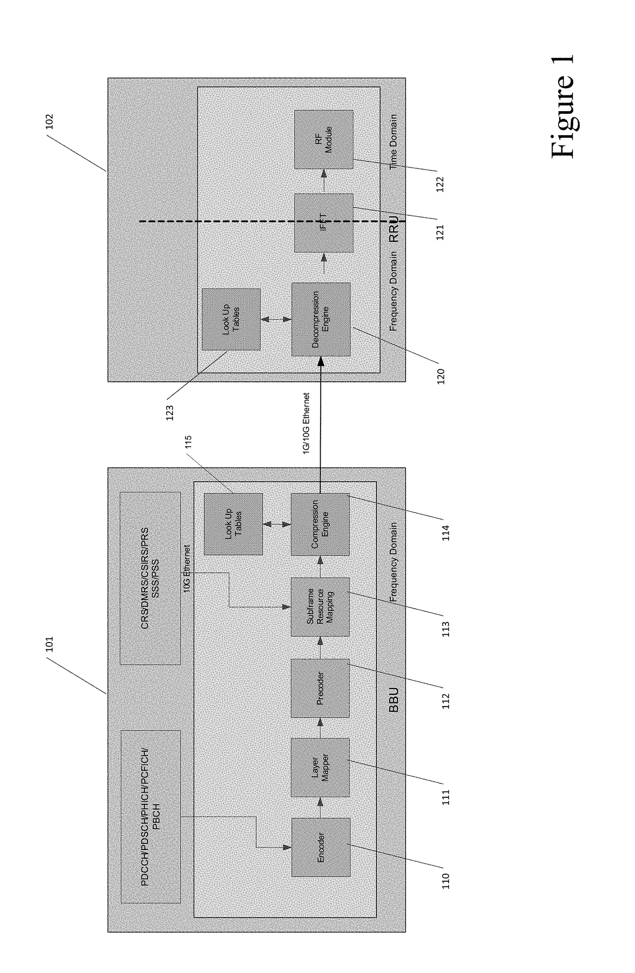
[0025]Certain embodiments provide for a fronthaul interface communication approach between two network entities, for example, a BBU and an RRU, which includes frequency domain data. Frequency domain data over a fronthaul interface may allow for lower bandwidth usage and more delay / jitter tolerance as compared to traditional time domain data approaches, such as CPRI and OBSAI. In part, this may be because smaller traffic takes a shorter time to be transported, which leads to smaller delays. Smaller traffic can also be less likely to block, or to be blocked by, other traffic sharing the same physical link, which leads to smaller jitters.

[0026]Frequency domain traffic bandwidth may be further reduced using compression techniques, in some embodiments. Compression can act to further reduce transport latency and signal jitters. In addition, in some embodiments compression can allow for more fronthaul traffic to be aggregated together to be transported over a long haul fiber, which may be ...


PUM


Abstract

Various communication systems may benefit from improved bandwidth compression techniques. For example, certain communication systems may benefit from a radio fronthaul traffic compression on a frequency domain data. A method can include identifying a composite waveform corresponding to a real component and an imaginary component of a frequency domain data at a first device. The method may also include causing a transmission of a value that represents the composite waveform to a second device from the first device.

Description

BACKGROUND[0001]Field[0002]Various communication systems may benefit from improved bandwidth compression techniques. For example, certain communication systems may benefit from a radio fronthaul traffic compression on a frequency domain data.[0003]Description of the Related Art[0004]In order to deal with the exponential nature of data network traffic, it can be helpful to increase the capacity of the communication network. One approach in dealing with the growing data demands may be to utilize a cloud Radio Access Network (C-RAN). In C-RAN, the functionality of a base station may be physically separated into separate network entity, for example, a baseband unit (BBU) and a remote radio unit (RRU). The BBU, which is responsible for signal processing, can be put in a single, centralized location. The RRUs, on the other hand, are responsible for receiving the processed signal from the BBU, and propagating the signal. The RRUs may be placed in different locations, depending on the deman...

Claims


Application Information

Patent Timeline
Patent Type & Authority Applications(United States)
IPC IPC(8): H04L29/06H04L12/811
CPCH04L47/38H04L69/04H03M7/3066H04B1/66H04L27/3405H04B10/25758H04L69/06
Inventor YANG, ROYRASKY, PHILLIPJEANES, TIMOTHYSCHMIDT, CHRISTOPHER
Owner NOKIA SOLUTIONS & NETWORKS OY
Why Eureka
Try Eureka