Aircraft, aircraft engine, and aircraft engine nacelle

a technology of aircraft engine and nacelle, which is applied in the direction of aircraft power plants, movable aircraft element position indicators, power plant types, etc., can solve the problems of high cost and time, and achieve the effect of suppressing cost and time necessary

Active Publication Date: 2017-08-24
MITSUBISHI AIRCRAFT
View PDF2 Cites 6 Cited by
  • Summary
  • Abstract
  • Description
  • Claims
  • Application Information

AI Technical Summary

Benefits of technology

The present invention is a system that uses the mechanical state of the engine nacelle to determine whether or not to output light emitted from light emitting sections. This eliminates the possibility of failure and ensures high reliability as the state of locking is visually confirmed. The invention allows a maintenance crew to easily detect the unlocked state of the cowl member, even at a distance from the airframe. This saves time and cost as measures against forgetting of locking of the cowl member are not necessary.

Problems solved by technology

This necessitates much cost and time.

Method used


Image

  • Aircraft, aircraft engine, and aircraft engine nacelle
  • Aircraft, aircraft engine, and aircraft engine nacelle
  • Aircraft, aircraft engine, and aircraft engine nacelle

Examples


Embodiment Construction

[0040]An embodiment of the present invention is described below with reference to accompanying drawings.

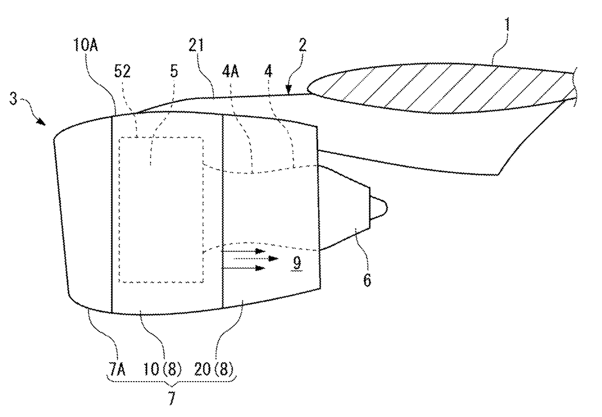
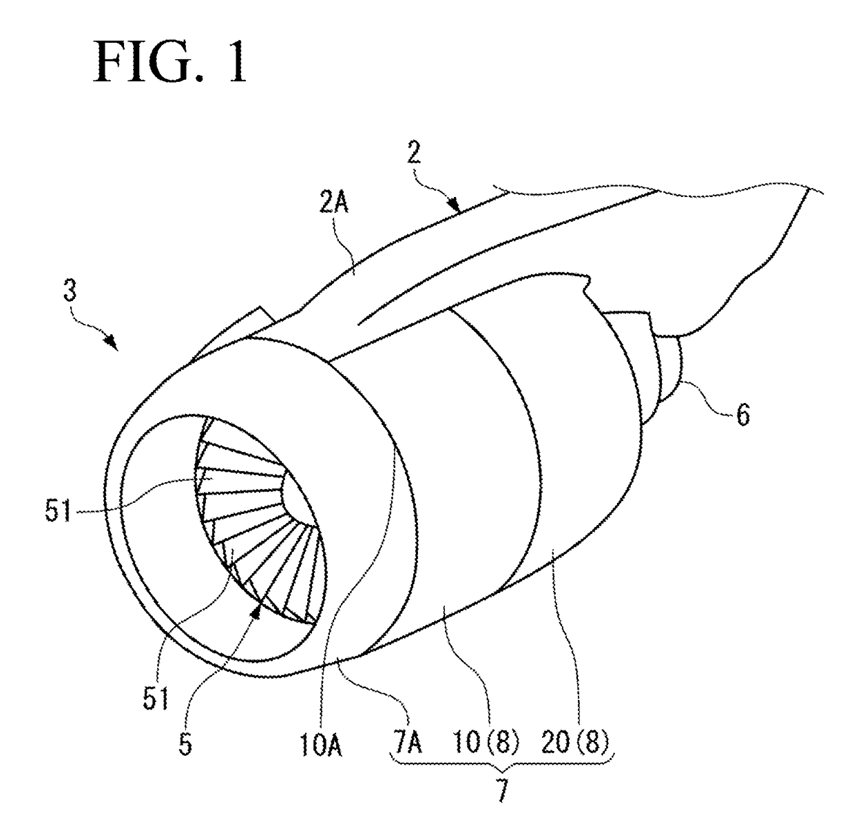
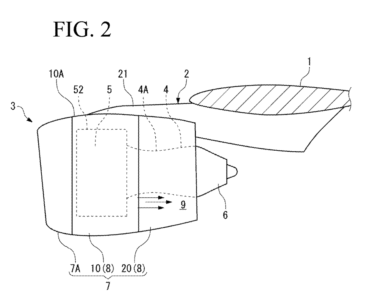
[0041]As illustrated in FIG. 1 and FIG. 2, an engine pylon 2 is attached on the bottom side of a main wing 1 (FIG. 2) of an aircraft, and an engine 3 is supported to the main wing 1 by the engine pylon 2.

[0042]In the drawings including FIG. 1 and FIG. 2, the engine 3 that is supported to the main wing 1 on left side (a left wing) is illustrated.

[0043]The engine pylon 2 includes a pylon main body (not illustrated) and a fairing 2A. The pylon main body is a structural member, and the fairing 2A is an aerodynamic fairing provided in the pylon main body.

[0044]As illustrated in FIG. 2, the engine 3 is a turbo fan engine that includes a fan 5 on the front side of an engine core 4 to be supplied with fuel.

[0045]In the present specification, side provided with the fan 5 in the engine 3 is defined as “front”, and side opposite thereto is defined as “rear”.

[0046]The engine 3 includes an eng...


PUM


Abstract

To surely grasp an unlocked state of a cowl member while suppressing cost and time necessary for measures against forgetting of locking of an engine nacelle. An aircraft according to the present invention includes: an engine (3) that includes an engine main body (4, 5) outputting thrust force and an engine nacelle (7) surrounding the engine main body (4, 5); an engine pylon (2) that supports the engine main body (4, 5) to a main wing (1) and axially supports a cowl member (8) to be openable, the cowl member (8) configuring the engine nacelle (7); a locking part (30) that locks the cowl member (8) of the engine nacelle (7) in a closed state; and one or more light emitting sections (15) that are disposed inside the cowl member (8) and show an unlocked state of the cowl member (8).

Description

BACKGROUND OF THE INVENTION[0001]Field of the Invention[0002]The present invention relates to an aircraft, an aircraft engine, and an engine nacelle that is opened and closed for maintenance of the engine of the aircraft.[0003]Description of the Related Art[0004]An engine nacelle of an aircraft is divided into two parts along an axis line, and an airframe side cowl member and an outer side cowl member are respectively opened to both sides through hinges that are attached to an engine pylon. Accessories and various gauges that are provided in the engine are maintained while the cowl members are supported in the opened state. Thereafter, rods supporting the cowl members are removed to cause the cowl members to pivot downward. Further, the airframe side cowl member and the outer side cowl member that have moved downward by own weight are brought into contact with each other by a latch handle, and latch members provided in the respective cowl members are locked with each other to lock t...

Claims


Application Information

Patent Timeline
Patent Type & Authority Applications(United States)
IPC IPC(8): B64D27/18B64D29/06B64D47/02B64C7/02
CPCB64D27/18B64D47/02B64D29/06B64C7/02B64D45/0005
Inventor OONISHI, TETSUYASHIMOJO, MASAHIROSUZUKI, TAKANORI
Owner MITSUBISHI AIRCRAFT
Why Eureka
Try Eureka