Systems and Methods for Dynamic Calibration of Array Cameras

a technology of dynamic calibration and array cameras, applied in the field of camera arrays, can solve the problems of difficulty in simultaneously capturing the collection of 2d images of scenes that form a light field

Active Publication Date: 2017-08-24
FOTONATION LTD
View PDF1 Cites 68 Cited by
  • Summary
  • Abstract
  • Description
  • Claims
  • Application Information

AI Technical Summary

Benefits of technology

[0016]In a still yet further embodiment, utilizing the residual vectors determined using the additional set of images further includes utilizing the residual vectors determined using the addi...

Problems solved by technology

Due to practical constraints, it is typically difficult to simultaneo...

Method used


Image

  • Systems and Methods for Dynamic Calibration of Array Cameras
  • Systems and Methods for Dynamic Calibration of Array Cameras
  • Systems and Methods for Dynamic Calibration of Array Cameras

Examples


Embodiment Construction

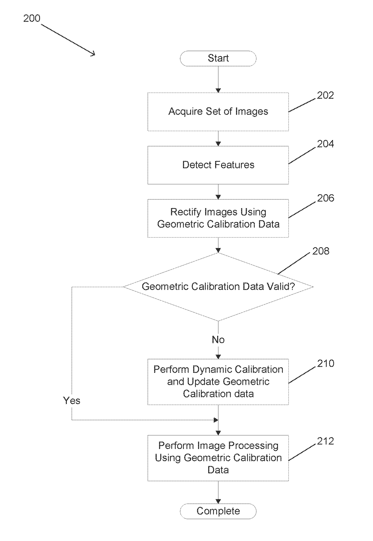
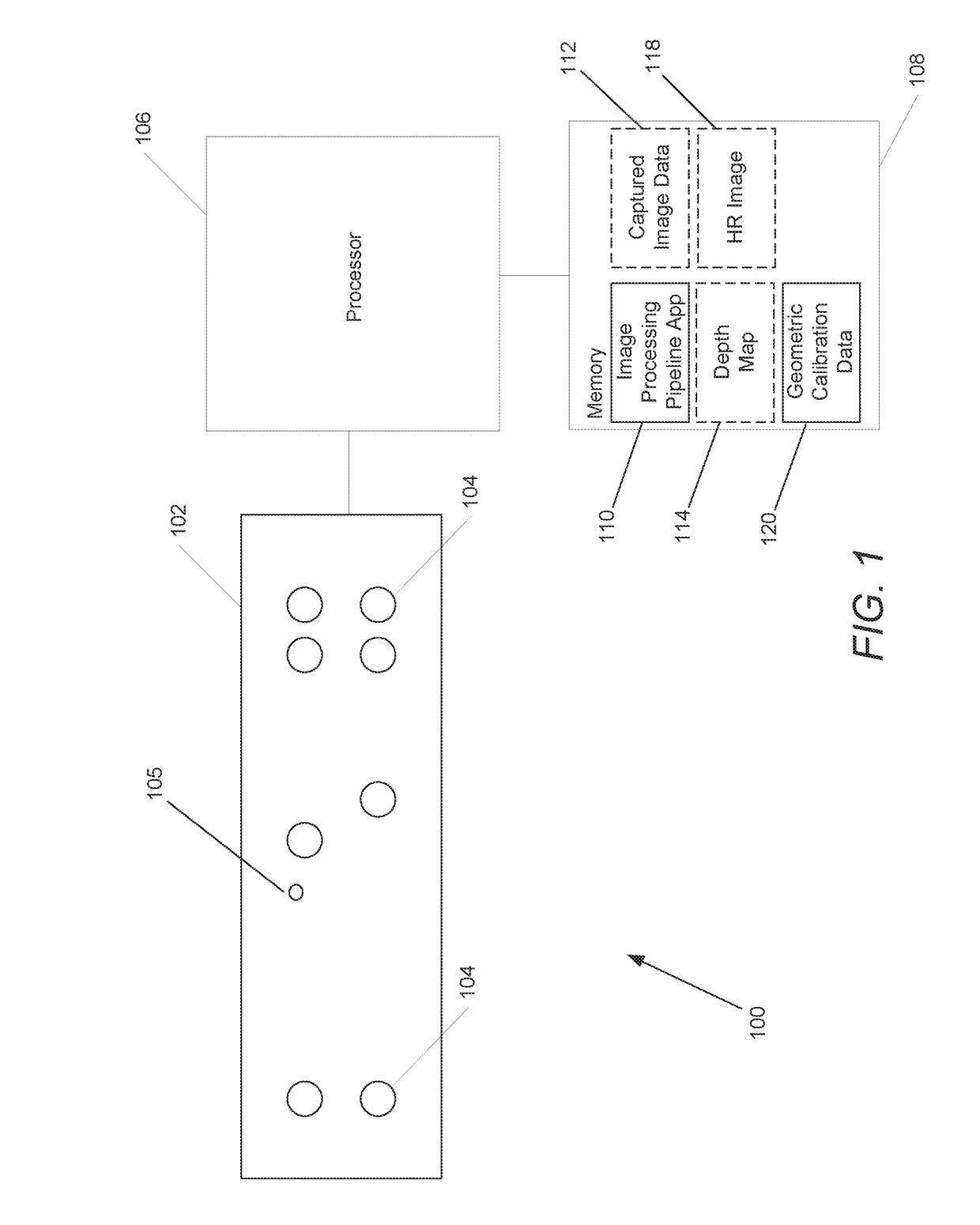
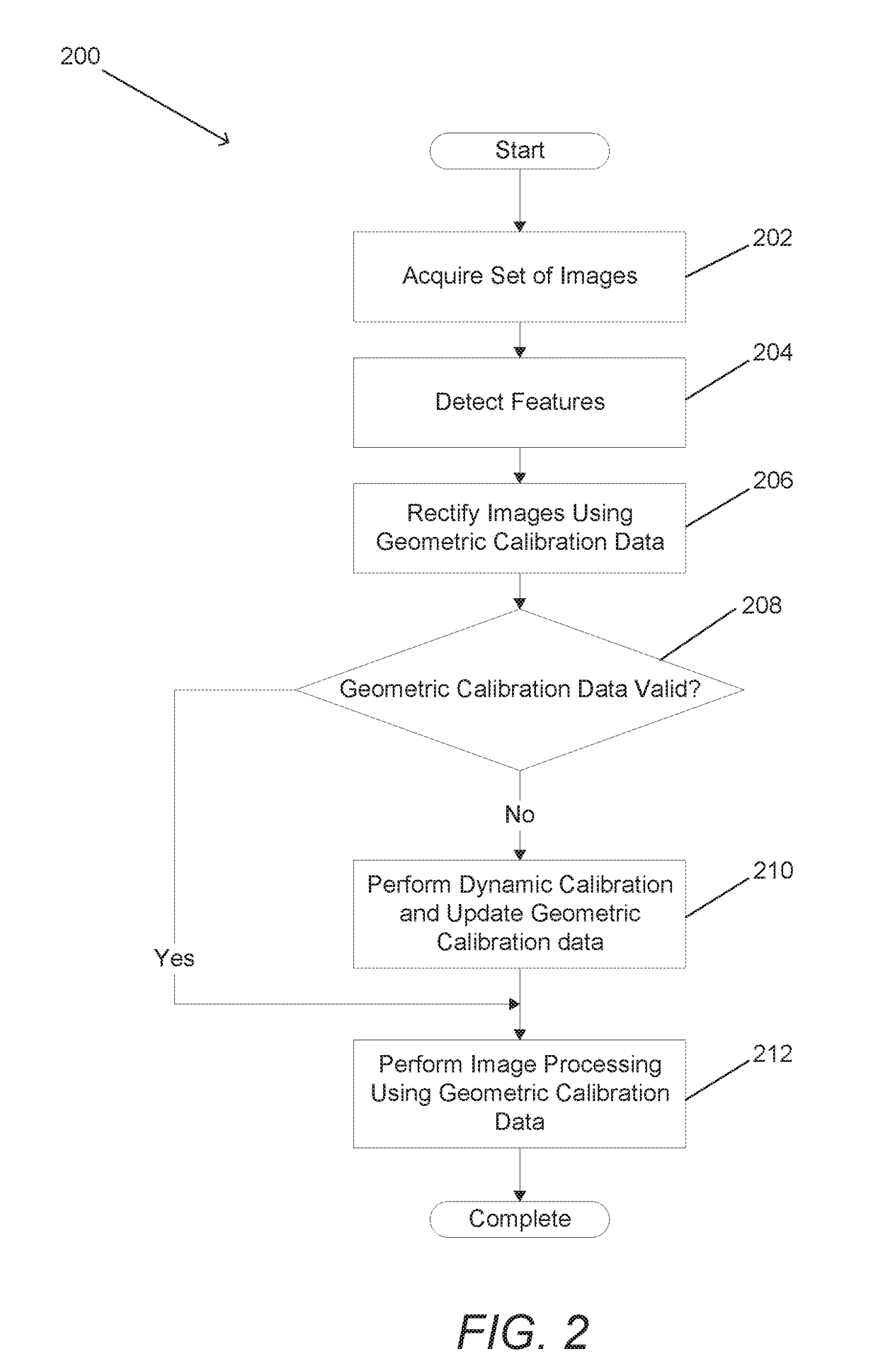
[0032]Turning now to the drawings, systems and methods for dynamically calibrating camera arrays in accordance with embodiments of the invention are illustrated. Multi-camera systems are increasingly gaining popularity for various applications and their correct functionality depends on an ability to precisely register images captured by the cameras with respect to each other. The complexity of registering the various images to each other is reduced significantly by rectifying the images. This usually relies on an offline calibration process to capture information concerning the scene independent shifts of corresponding pixels that are introduced by the cameras in the array as a result of their construction (e.g. manufacturing variations in lens characteristics and / or in camera assembly), relative positions, and orientations (often referred to as the geometry of the array). In reality, the mechanical structures to which cameras in an array are mounted respond differently to various f...


PUM


Abstract

Systems and methods for dynamically calibrating an array camera to accommodate variations in geometry that can occur throughout its operational life are disclosed. The dynamic calibration processes can include acquiring a set of images of a scene and identifying corresponding features within the images. Geometric calibration data can be used to rectify the images and determine residual vectors for the geometric calibration data at locations where corresponding features are observed. The residual vectors can then be used to determine updated geometric calibration data for the camera array. In several embodiments, the residual vectors are used to generate a residual vector calibration data field that updates the geometric calibration data. In many embodiments, the residual vectors are used to select a set of geometric calibration from amongst a number of different sets of geometric calibration data that is the best fit for the current geometry of the camera array.

Description

FIELD OF THE INVENTION[0001]The present application relates generally to camera arrays and more specifically to the dynamic calibration of an array of cameras.BACKGROUND[0002]Binocular viewing of a scene creates two slightly different images of the scene due to the different fields of view of each eye. These differences, referred to as binocular disparity (or parallax), provide information that can be used to calculate depth in the visual scene, providing a major means of depth perception. The impression of depth associated with stereoscopic depth perception can also be obtained under other conditions, such as when an observer views a scene with only one eye while moving. The observed parallax can be utilized to obtain depth information for objects in the scene. Similar principles in machine vision can be used to gather depth information.[0003]Two cameras separated by a distance can take pictures of the same scene and the captured images can be compared by shifting the pixels of two...

Claims


Application Information

Patent Timeline
IPC IPC(8): H04N17/00H04N5/247G06T5/00
CPCH04N17/002H04N5/247G06T5/006G06T2207/10012G06T2207/10052G06T7/80H04N23/00H04N23/90
Inventor CIUREA, FLORIANLELESCU, DANCHATTERJEE, PRIYAM
Owner FOTONATION LTD
Why Eureka
Try Eureka