
Device and method for weighted sparse inversion for seismic processing

a technology of sparse inversion and seismic processing, applied in the field of methods and systems for processing seismic data, can solve the problems of insufficient resolution of inversion schemes, inability to provide accurate, and inability to separate primary and multiple areas

Inactive Publication Date: 2017-08-31
CGG SERVICES SAS
View PDF12 Cites 24 Cited by
  • Summary
  • Abstract
  • Description
  • Claims
  • Application Information

AI Technical Summary

Benefits of technology

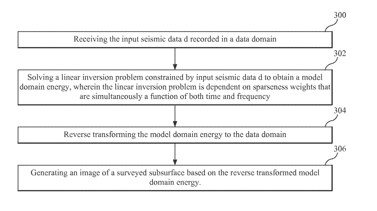
This patent describes a method for processing seismic data by solving an inversion problem to obtain a model of the underground formations. This model is then transformed back to the original data domain to create an image of the surveyed area. A computing device implements this method using instructions executed by a processor. The technical effect is that this method improves the accuracy and quality of seismic imaging, allowing for more reliable and accurate mapping of underground formations.

Problems solved by technology

While this profile does not provide an accurate location for oil and gas, it suggests, to those trained in the field, the presence or absence of oil and / or gas.
However, there are problems with the traditional inversion schemes as now discussed.
While this approach is very effective, the use of low frequencies may not have high enough resolution to separate areas of primary and multiples where they are not distinctive enough in moveout.
However, sparseness in time is not always of advantage as in the case of diffracted multiples, or after the application of other demultiple methods or migration, as the multiples may be fragmented and no longer be sparse in time.
However, the sparseness has no resolution in time and the time windowing often required to get this to work properly can cause edge effects particularly for low frequencies.
In addition, aliasing at slownesses where there are primary events cannot be adequately avoided.
While time domain implementations solve some of these problems, they no longer have the ability to vary the sparseness with frequency.

Method used


Image

  • Device and method for weighted sparse inversion for seismic processing
  • Device and method for weighted sparse inversion for seismic processing
  • Device and method for weighted sparse inversion for seismic processing

Examples


Embodiment Construction

[0036]The following description of the exemplary embodiments refers to the accompanying drawings. The same reference numbers in different drawings identify the same or similar elements. The following detailed description does not limit the invention. Instead, the scope of the invention is defined by the appended claims. The following embodiments are discussed, for simplicity, with regard to a Radon domain. However, the novel embodiments may be applied to other domains.

[0037]Reference throughout the specification to “one embodiment” or “an embodiment” means that a particular feature, structure or characteristic described in connection with an embodiment is included in at least one embodiment of the subject matter disclosed. Thus, the appearance of the phrases “in one embodiment” or “in an embodiment” in various places throughout the specification is not necessarily referring to the same embodiment. Further, the particular features, structures or characteristics may be combined in any...


PUM


Abstract

Computing device, computer instructions and method for processing input seismic data d. The method includes receiving the input seismic data d recorded in a data domain, solving a linear inversion problem constrained by input seismic data d to obtain a model domain and its energy, wherein the linear inversion problem is dependent on sparseness weights that are simultaneously a function of both time and frequency, reverse transforming the model domain energy to the data domain, and generating an image of a surveyed subsurface based on the reverse transformed model domain energy.

Description

CROSS-REFERENCE TO RELATED APPLICATIONS[0001]The present application is related to and claims the benefit of priority of U.S. Provisional Application 62 / 079,781, filed Nov. 14, 2014; U.S. Provisional Application 62 / 110,933, filed Feb. 2, 2015; and U.S. Provisional Application 62 / 183,255, filed Jun. 23, 2015, the entire contents of which are incorporated herein by reference.BACKGROUND[0002]Technical Field[0003]Embodiments of the subject matter disclosed herein generally relate to methods and systems for processing seismic data for improving an image of a surveyed subsurface and, more particularly, to mechanisms and techniques related to an inversion scheme for the processing of seismic data using sparseness weights that are a function of time and frequency.[0004]Discussion of the Background[0005]Seismic data acquisition and processing generates a profile (image) of the geophysical structure (subsurface) under the ground. While this profile does not provide an accurate location for oi...

Claims


Application Information

Patent Timeline
Patent Type & Authority Applications(United States)
IPC IPC(8): G01V1/28G01V1/36G01V1/32
CPCG01V1/282G01V2210/46G01V1/364G01V1/32G01V2210/30G01V2210/21G01V1/28G01V2210/23G01V2210/22
Inventor POOLE, GORDON
Owner CGG SERVICES SAS
Learn More