Elastic wave device and manufacturing method for the same

Active Publication Date: 2017-08-31
MURATA MFG CO LTD
View PDF0 Cites 10 Cited by
  • Summary
  • Abstract
  • Description
  • Claims
  • Application Information

AI Technical Summary

Benefits of technology

[0018]With the elastic wave devices and the manufacturing methods therefor according to various preferred embodiments of the present invention, at least a portion of the

Problems solved by technology

In this case, a decrease in excitation effic

Method used


Image

  • Elastic wave device and manufacturing method for the same
  • Elastic wave device and manufacturing method for the same
  • Elastic wave device and manufacturing method for the same

Examples


Embodiment Construction

[0032]Hereinafter, the present invention will be clarified through description of specific preferred embodiments of the present invention with reference to the drawings.

[0033]It is to be noted that the preferred embodiments described in the present specification are merely examples and configurations thereof can be partly replaced or combined between different preferred embodiments.

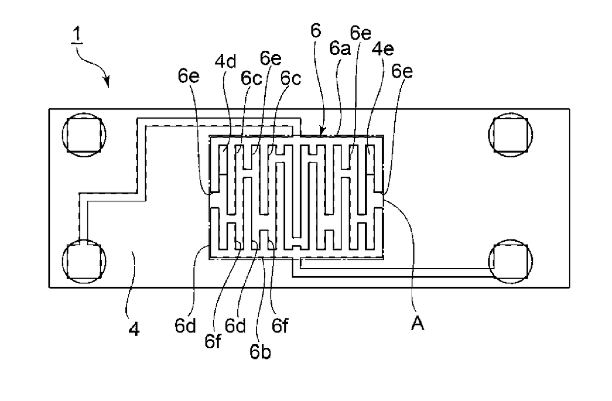
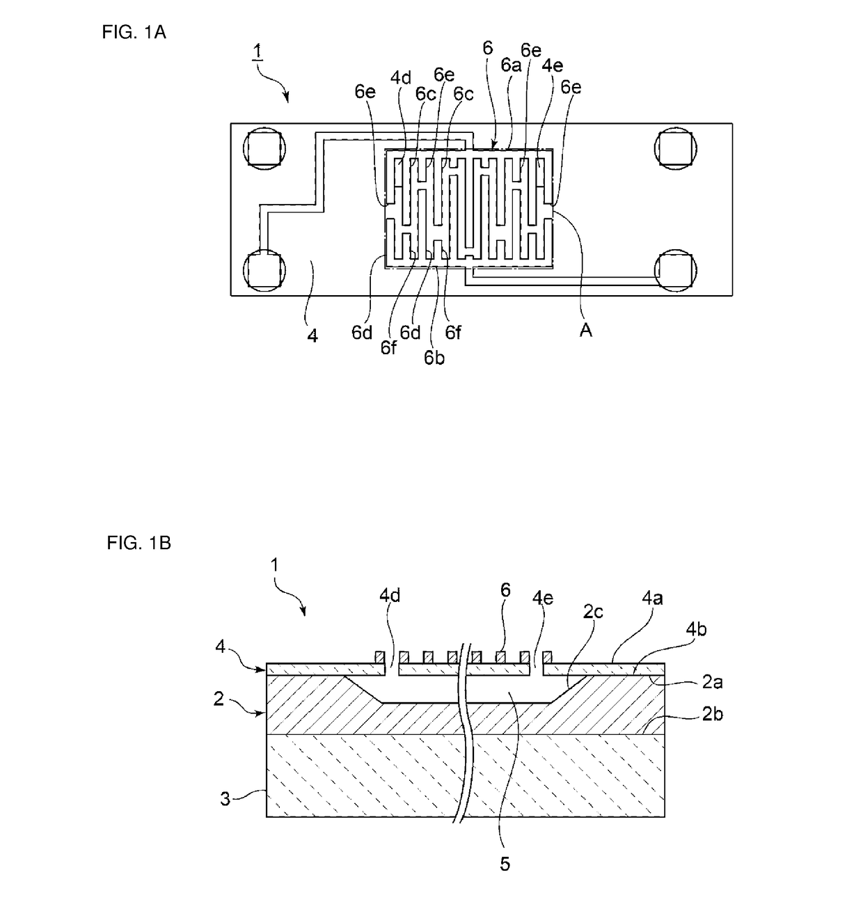
[0034]FIGS. 1A and 1B are respectively a plan view and a partially cutout cross-sectional front view of an elastic wave device according to a first preferred embodiment of the present invention.

[0035]An elastic wave device 1 is an elastic wave device structured to generate and use Lamb waves as a plate wave, for example. The elastic wave device 1 includes a support substrate 2. The support substrate 2 includes an upper surface 2a and a lower surface 2b. In the upper surface 2a, there is provided a recess 2c that is opened toward the upper surface 2a. The support substrate 2 can include an appropriate diel...


PUM


Abstract

In an elastic wave device, a piezoelectric substrate is laminated on a support substrate including a recess. On one of a first principal surface and a second principal surface of the piezoelectric substrate, a functional electrode including an IDT electrode is provided. Passing-through sections are provided in the piezoelectric substrate and connected to a hollow section enclosed by the recess and the piezoelectric substrate. In a plan view of the piezoelectric substrate seen from the first principal surface, at least a portion of the passing-through sections is inside a minimum rectangular or substantially rectangular region encompassing an outer circumference of a region including the functional electrode.

Description

CROSS REFERENCE TO RELATED APPLICATIONS[0001]This application claims the benefit of priority to Japanese Patent Application No. 2014-256263 filed on Dec. 18, 2014 and is a Continuation Application of PCT Application No. PCT / JP2015 / 082764 filed on Nov. 20, 2015. The entire contents of each application are hereby incorporated herein by reference.BACKGROUND OF THE INVENTION[0002]1. Field of the Invention[0003]The present invention relates to elastic wave devices and manufacturing methods for the same.[0004]2. Description of the Related Art[0005]Various types of elastic wave devices using plate waves have been proposed. An elastic wave device making use of plate waves and including a hollow section is disclosed in Japanese Unexamined Patent Application Publication No. 2014-13991 and WO 2012 / 073871 A1. In Japanese Unexamined Patent Application Publication No. 2014-13991, at a time of forming a hollow section, a sacrificial layer is formed in advance. A piezoelectric thin film is laminate...

Claims


Application Information

Patent Timeline
IPC IPC(8): H03H9/145H03H3/08H03H9/25
CPCH03H9/14541H03H3/08H03H9/25H03H3/02H03H9/02047H03H9/02228H03H2003/021
Inventor OMURA, MASASHIKIMURA, TETSUYAKISHIMOTO, YUTAKA
Owner MURATA MFG CO LTD
Why Eureka
Try Eureka