Mechanical locking system for floorboards

Active Publication Date: 2017-09-07
VÄLINGE INNOVATION AB
View PDF7 Cites 3 Cited by
  • Summary
  • Abstract
  • Description
  • Claims
  • Application Information

AI Technical Summary

Problems solved by technology

These systems and the manufacturing methods suffer from a number of drawbacks, which are above all related to cost and function.
This usually results in lower locking strength and difficulties in laying or de

Method used


Image

  • Mechanical locking system for floorboards
  • Mechanical locking system for floorboards
  • Mechanical locking system for floorboards

Examples


first embodiment

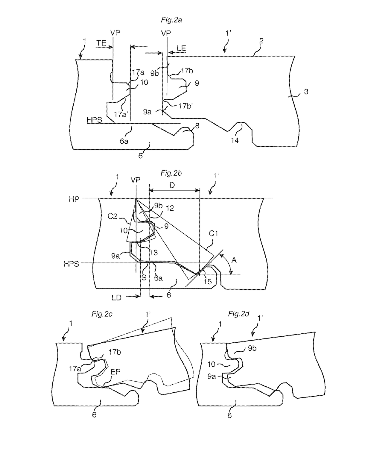
[0112]floorboards 1, 1′ provided with a mechanical locking system according to the invention is shown in FIGS. 2a-2d.

[0113]A building panel is shown that in this embodiment is a floorboard comprising a surface 2 attached to, or of, a core 3. The floorboard is provided with a locking system for vertical and horizontal locking of a first 1 and a second edge 1′ of adjacent panel edges. The upper parts of two edges 1,1′ of two joined floorboards together define a vertical plane VP. The vertical plane is perpendicular to a horizontal plane HP that is parallel to the panel surface. The locking system is configured to lock the edges 1, 1′ by angling two adjacent edges relative each other. The locking system comprises a tongue 10 made in one piece with said core 3 that cooperates with tongue groove 9 in the adjacent edge 1′ for vertical locking. The tongue groove 9 comprises a lower lip 9a and an upper lip 9b above the lower lip. The first edge 1 comprises a strip 6 made in one piece with ...

embodiment 1

[0169]2. The method , wherein the method comprises the step of forming a first vertically open groove (19), through a rear side of the board and an offset second vertically open groove (19), through the front side of the board.

embodiment 2

[0170]3. The method , wherein the first vertically open groove (18) is formed by a fixed tool or a saw blade.

[0171]4. The method as in any one of embodiments 2 or 3, wherein the second vertically open groove (19) is formed by a fixed tool or a saw blade.

[0172]5. The method as in any one of the embodiments 2-4, wherein the method comprises the step of forming, by a fixed tool (22b), a first horizontally extending groove that extends horizontally under the front side and / or the rear side of the board.


PUM

PropertyMeasurementUnit
Angleaaaaaaaaaa
Distanceaaaaaaaaaa

Abstract

Building panels, especially floor panels are shown, which are provided with a locking system that is configured to lock the adjacent edges by angling and that have a tongue and a strip on the same edge, and a method to divide a board and produce such building panels. A method for dividing a floor element, into a first floor panel and a second floor panel, said floor element including a core provided with a decorative surface layer and a balancing layer, wherein the method includes the step of forming, through the balancing layer or the decorative surface layer, a second groove by displacing the floor element past a fixed tool.

Description

CROSS REFERENCE TO RELATED APPLICATIONS[0001]The present application is a continuation of U.S. application Ser. No. 13 / 920,647, filed on Jun. 18, 2013, which claims priority to U.S. Provisional Application No. 61 / 661,645, filed on Jun. 19, 2012, and claims the benefit of Swedish Application No. 1250656-4, filed on 19 Jun. 2012, Swedish Application No. 1250691-1, filed on 26 Jun. 2012, and Swedish Application No. 1350027-7, filed on 11 January 2013. The entire contents of each of U.S. application Ser. No. 13 / 920,647, U.S. Provisional Application No. 61 / 661,645, Swedish Application No. 1250656-4, Swedish Application No. 1250691-1, and Swedish Application No. 1350027-7 are hereby incorporated herein by reference in their entirety.TECHNICAL FIELD[0002]Embodiments of the invention generally relate to the field of mechanical locking systems for building panels, especially floorboards. Embodiments of the invention relate to floorboards provided with such locking systems and methods for mak...

Claims


Application Information

Patent Timeline
IPC IPC(8): E04B5/02B27F1/02B27M3/04E04F15/02
CPCE04B5/02E04F15/02038E04F2201/0153B27F1/02B27M3/04E04F2201/0115E04F2201/025Y10T29/49815Y10T29/49819Y10T29/49817E04F15/041E04F15/042E04G23/006
Inventor PERVAN, DARKOPALSSON, AGNE
Owner VÄLINGE INNOVATION AB
Why Eureka
Try Eureka