
A battery module charging and discharging control method and a battery system

Active Publication Date: 2017-09-21
CHAN KK +1
View PDF4 Cites 6 Cited by
  • Summary
  • Abstract
  • Description
  • Claims
  • Application Information

AI Technical Summary

Benefits of technology

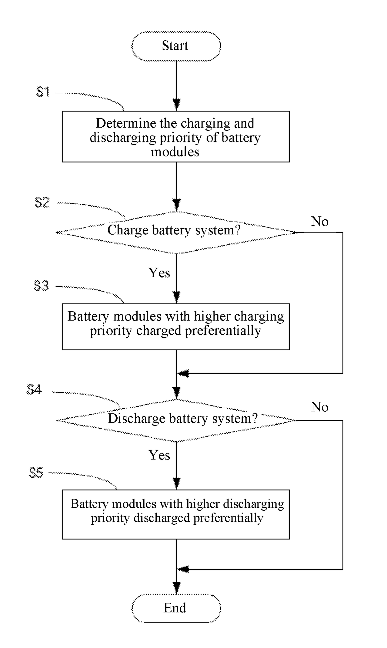
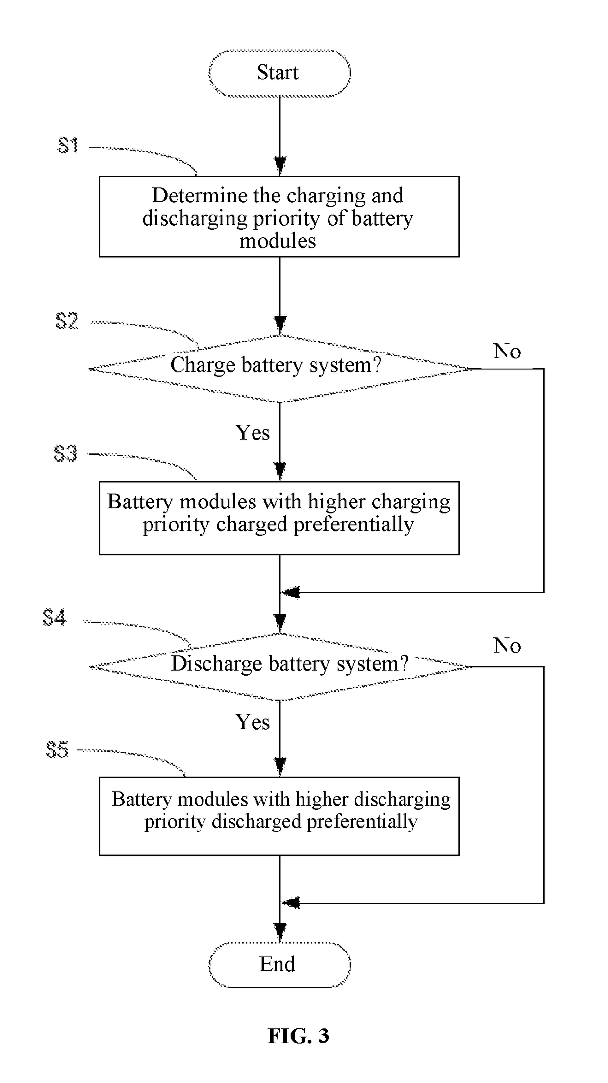
The present invention provides a battery module charging and discharging control method that reduces manual labor required for the recharging of the battery system and the replacement of battery modules. The method determines the charging and discharging priorities of multiple battery modules based on their difficulty of unloading, loading, and / or replacement. This results in increased states of charge of battery modules that are more difficult to unload, load, and / or replace, and decreased states of charge of battery modules that are easier to unload, load, and / or replace. This reduces the frequency of unloading and replacement of battery modules during charging, which in turn reduces the manual labor required for the charging and replacement of battery modules.

Problems solved by technology

However, electric energy stored in a single battery cell is often limited, and thus a battery system containing a plurality of battery modules is typically used to power an automobile or a device of larger power consumption.
Due to the size limitation of the battery modules, the electric energy stored in each battery module is limited; hence the battery modules in use would be quickly depleted and need frequent recharging or replacement.
In certain complex cases, probably only trained personnel can use the electrical cables properly to make the proper connection between the battery modules and the charging equipment.
Also, this cable connection task is often laborious and time consuming, making battery module charging exceedingly inconvenient.
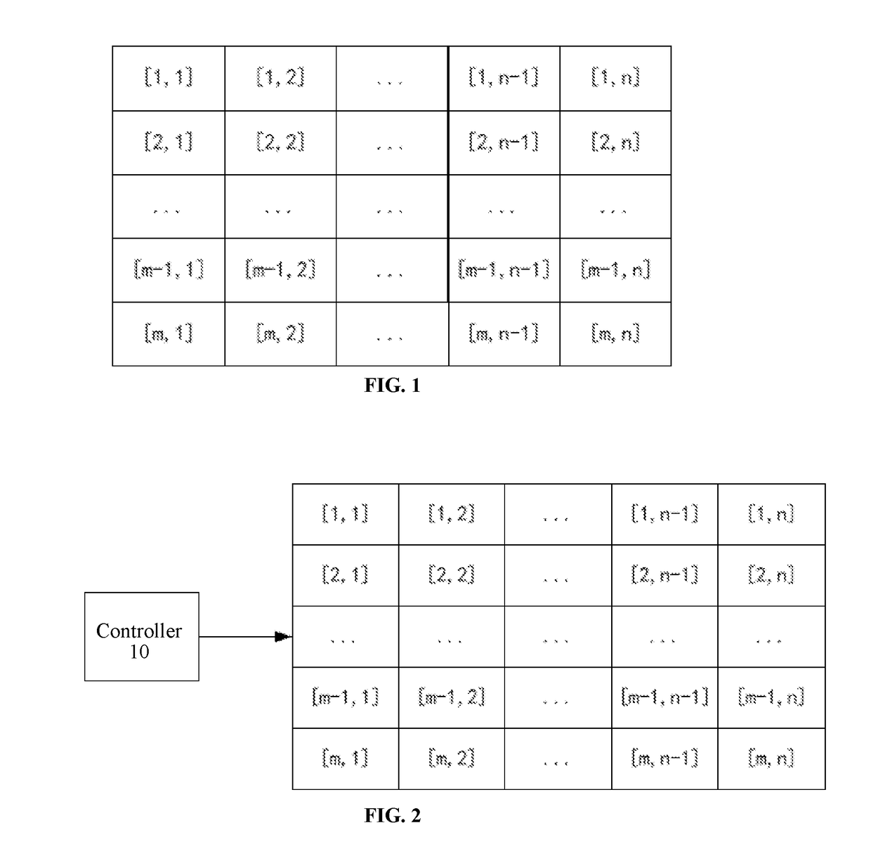
For example, as shown in FIG. 1, the opening for loading and unloading of battery modules is located on the top of the battery system container, making the unloading and loading of the battery modules located at the bottom of the container quite difficult, especially for the last row of battery modules (e.g. [m, 1], [m, 2], .
Lastly, in some battery systems, battery modules can only be recharged after being unloaded from their battery systems.
As the battery modules are usually heavy, the unloading and loading of battery modules may require much manual labor, in turn resulting in low efficiency in the unloading and reloading of the battery modules.
In particular, for example, the battery modules located at the bottom of the container in FIG. 1 are difficult to unload and reload, leading to low efficiency in and excessive manual labor for the recharging of the battery system.
This obviously also requires much manual labor, especially in cases where the battery modules to replace are located at the bottom of a container such as that shown in FIG. 1.

Method used


Image

  • A battery module charging and discharging control method and a battery system
  • A battery module charging and discharging control method and a battery system
  • A battery module charging and discharging control method and a battery system

Examples


Embodiment Construction

[0025]In the following description, battery systems and methods of charging and discharging battery and the likes are set forth as preferred examples. It will be apparent to those skilled in the art that modifications, including additions and / or substitutions may be made without departing from the scope and spirit of the invention. Specific details may be omitted so as not to obscure the invention; however, the disclosure is written to enable one skilled in the art to practice the teachings herein without undue experimentation.

[0026]In accordance with an embodiment of the present invention, the battery system comprises a plurality of battery modules that can be independently unloaded and loaded. As shown in FIG. 2, the plurality of battery modules are arranged in m rows by n columns, and housed in a container. For example, when a battery system is used in an electric vehicle, battery modules are housed in a specific container of the electric vehicle. Of course, the battery system ca...


PUM


Abstract

A battery module charging and discharging control method comprising: determining the charging priority of battery modules in a battery system; raising the charging priority of the battery modules that are more difficult to unload, load, and / or replace; lowering the charging priority of the battery modules that are easier to unload, load, and / or replace; causing the battery modules with higher charging priority to take precedence over the battery modules with lower charging priority during the charging control of the battery modules; determining the discharging priority of the battery modules; raising the discharging priority of the battery modules that are easier to unload, load, and / or replace; and lowering the discharging priority of the battery modules that are more difficult to unload, load, and / or replace; causing the battery modules with higher discharging priority to take precedence over the battery modules with lower discharging priority during the discharging control of the battery modules.

Description

BACKGROUND[0001]Batteries are a widely used means for storing electric energy. At present, many instruments, electronic equipment, industrial equipment, automobiles, and more use batteries for their power supplies. However, electric energy stored in a single battery cell is often limited, and thus a battery system containing a plurality of battery modules is typically used to power an automobile or a device of larger power consumption. A battery module can be a single battery cell or a component that is severable from the battery system and can be individually unloaded, loaded, and replaced.[0002]For example, shown in FIG. 1 is a battery system containing a plurality of battery modules. The battery modules in this battery system are arranged in m rows and n columns, so the number of the battery modules is m×n. Due to the size limitation of the battery modules, the electric energy stored in each battery module is limited; hence the battery modules in use would be quickly depleted and...

Claims


Application Information

Patent Timeline
IPC IPC(8): H02J7/00
CPCH02J7/0013H02J7/0003H01M10/4207H01M10/44H01M10/482H01M2010/4271H02J7/0014Y02E60/10
Inventor CHANLEONG, SOK LEING, SING
Owner CHAN KK
Learn More