Discharge Portion Liner Attachment Structure for Vertical Shredder

Active Publication Date: 2017-04-06
KUBOTA ENVIRONMENTAL ENG CORP
View PDF19 Cites 0 Cited by
  • Summary
  • Abstract
  • Description
  • Claims
  • Application Information

AI Technical Summary

Benefits of technology

[0013]The present invention is made in view of the conventional problem described above and an object of the present invention is to provide a discharge portion liner attachment structure

Problems solved by technology

When such an opening is employed, sufficient strength to hold heavy components installed above the discharge ring, such as the cylindrical shell, is difficult to achieve.
As a result, the structure might be complex and expensive due to the increase in the number of components.
Unfortunately, in this configuration, ones of the discharge ring liners close to the opening frequ

Method used


Image

  • Discharge Portion Liner Attachment Structure for Vertical Shredder
  • Discharge Portion Liner Attachment Structure for Vertical Shredder
  • Discharge Portion Liner Attachment Structure for Vertical Shredder

Examples


Example

[0039]A breaker liner attachment structure and a discharge portion liner attachment structure for a vertical shredder are described with reference to the drawings.

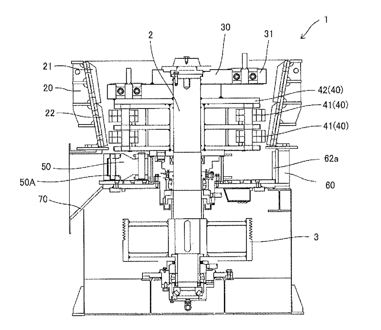
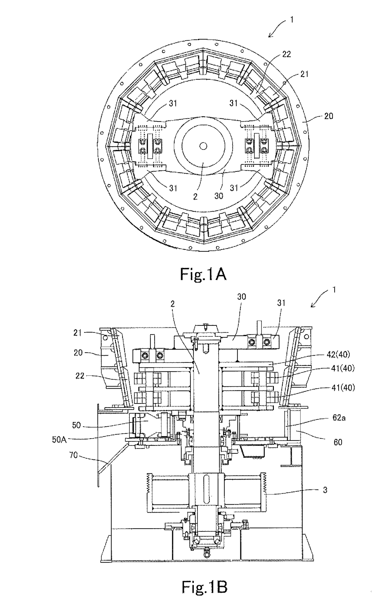
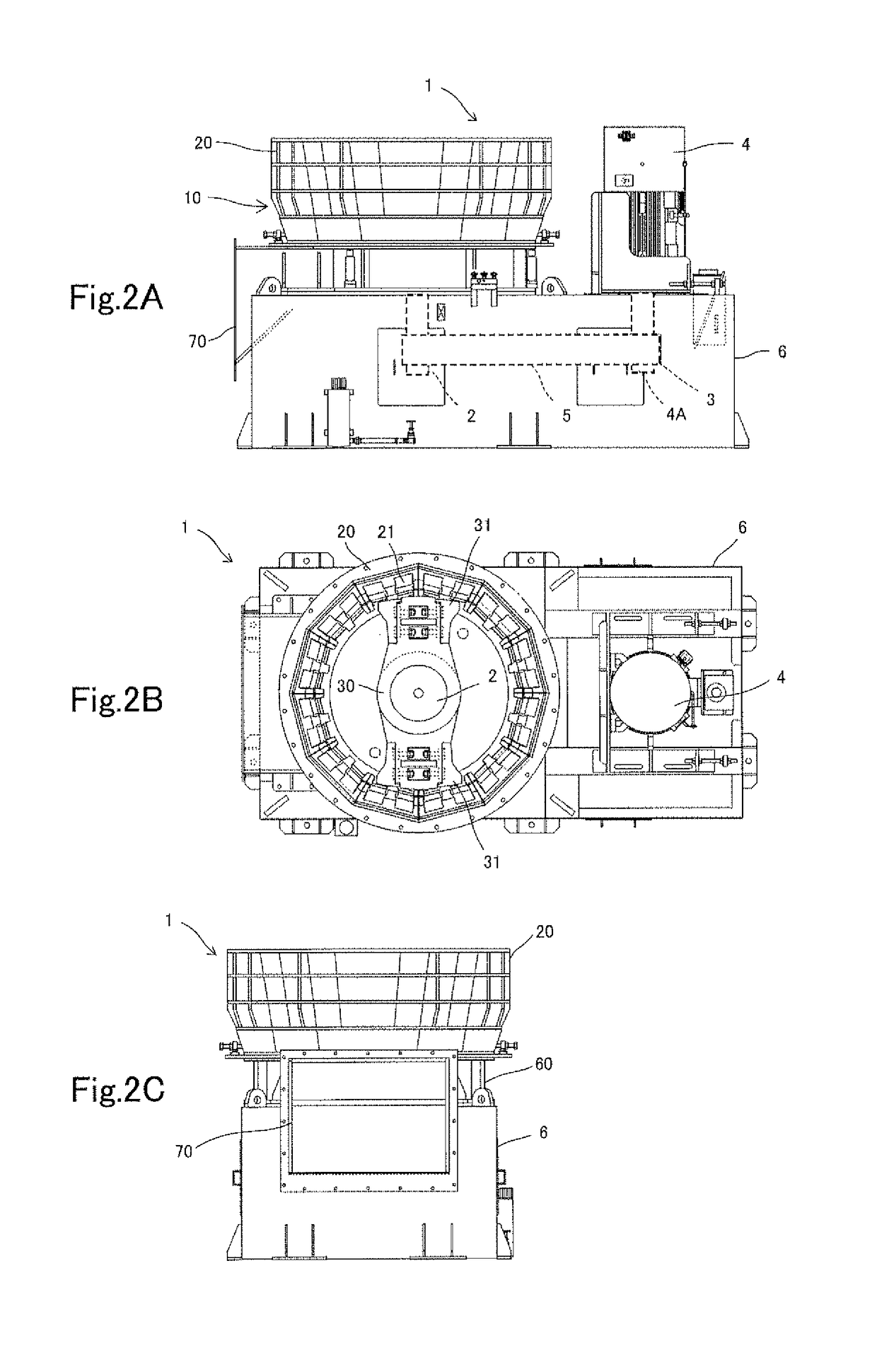
[0040]As illustrated in FIG. 2A, FIG. 2B, and FIG. 2C, a vertical shredder 1 is a device that performs a shredding process on a household electric appliance such as a refrigerator, and includes a motor 4 provided to a device frame 6 and a shredding process unit 10. The shredding process unit 10 includes components such as: a discharge ring 60 fixed to the device frame 6; a cylindrical shell 20 disposed above the discharge ring 60; and a breaker 30 rotatably accommodated in the cylindrical shell 20. A shredded material by the shredding process unit 10 is swept out through a discharge portion 70.

[0041]In the device frame 6, a pulley 3 attached to an output shaft 4A of the motor 4, is coupled to a pulley provided to a rotation shaft 2 of the shredding process unit 10 via a V belt 5 in a driving force transmittable manner. Thu...


PUM


Abstract

In a discharge portion liner attachment structure for a vertical shredder including a sweeper supported below a rotor in such a manner as to be coaxial with a rotation shaft, a discharge ring disposed on a circumference portion of the sweeper, and a discharge portion through which a shredding target object that has been swept out through an opening formed on a circumference wall of the discharge ring by a sweeping operation performed by the sweeper is discharged to outside, discharge portion liners are attached in such a manner as to protrude from a side of the discharge portion to a side of the discharge ring in such a manner as to cover edge portions of ones of the discharge ring liners on a side of the opening.

Description

CROSS-REFERENCE TO RELATED APPLICATIONS[0001]The present application claims priority under 35U.S.C.119 to Japanese Patent Application No. 2015-196802 filed on Oct. 2, 2015, the contents of this application are incorporated herein by reference in their entirety.BACKGROUND OF THE INVENTION[0002]Field of the invention[0003]The present invention relates to a discharge portion liner attachment structure for a vertical shredder that shreds discarded household electric appliances and the like.[0004]Description of the Related Art[0005]Vertical shredders are used as devices that perform a shredding process for recycling discarded household electric appliances such as a refrigerator that have been collected.[0006]The vertical shredder includes: a rotor that is supported on a rotation shaft rotating about a vertical axis; a cylindrical shell that is disposed on an outer side of the rotor in a radial direction in such a manner as to be concentric with the vertical axis, and has an inner circumf...

Claims


Application Information

Patent Timeline
IPC IPC(8): B02C13/286B02C13/14
CPCB02C13/286B02C2210/02B02C2013/28609B02C13/14B02C13/18B02C18/2216B02C2013/2825
Inventor SHIRAI, ATSUHIKOSHIBATA, KATSUYA
Owner KUBOTA ENVIRONMENTAL ENG CORP
Why Eureka
Try Eureka