Mounting frame for fuel cell stack

Inactive Publication Date: 2005-07-21
SHANGHAI SHENLI TECH CO LTD
View PDF3 Cites 19 Cited by
  • Summary
  • Abstract
  • Description
  • Claims
  • Application Information

AI Technical Summary

Benefits of technology

[0024] A primary object of the present invention is to provide a mounting device for congregated fuel cell stack, wherein the mounting frame is easy to mainta

Problems solved by technology

However, it is impossible to assemble a fuel cell stack comprising a plurality of sized electrode flow field plate to output such a powerful energy.
Unfortunately, such congregated, powerful fuel cell stacks could not be packaged or securely fixed according to the conventional packaging method as shown in FIG. 2.
This is due to the fact that

Method used


Image

  • Mounting frame for fuel cell stack
  • Mounting frame for fuel cell stack
  • Mounting frame for fuel cell stack

Examples


Example

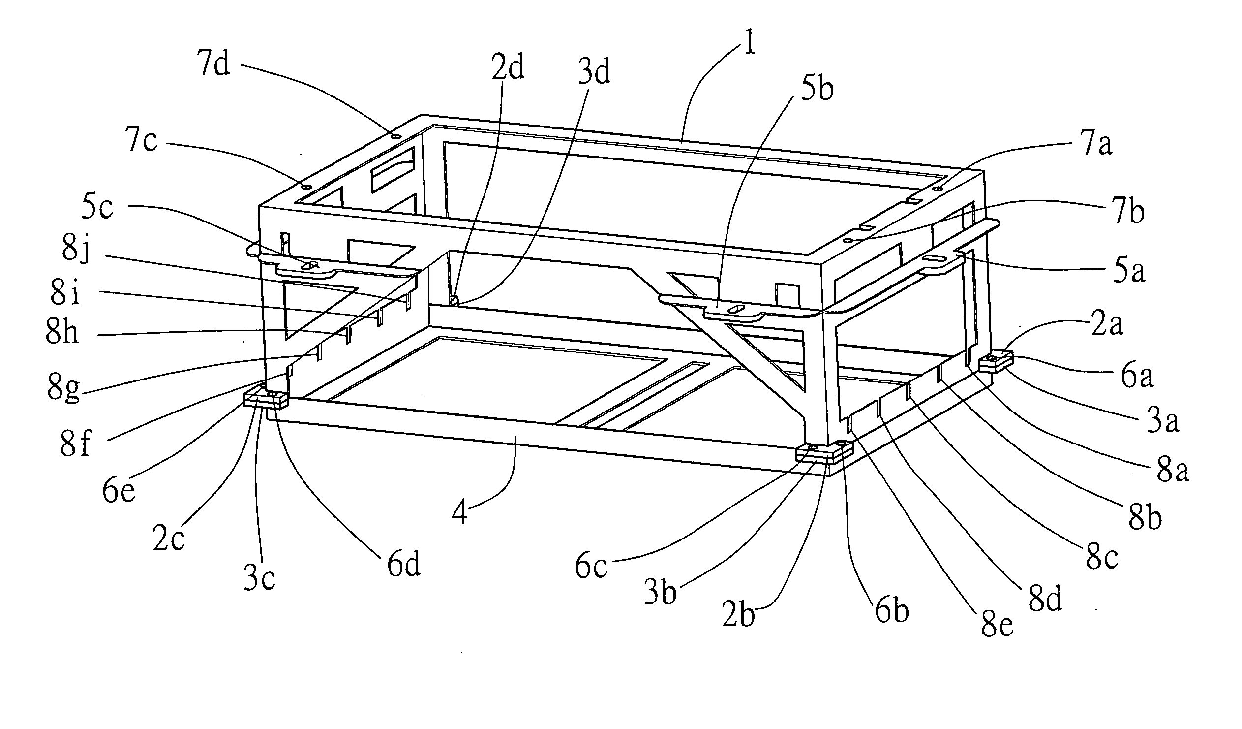
[0037] Referring to the FIGS. 3 to 7, the mounting frame for a congregated fuel cell stack according to the preferred embodiment of the present invention is illustrated, wherein the fuel cell stack generally comprises a plurality of fuel cell units, a pair of end plates sandwiching the fuel cell units, and reinforcing arm extended between the end plates to securely the fuel cell units therebetween. The mounting frame comprises a cell enclosure, a retention arrangement, and a locking arrangement.

[0038] The cell enclosure comprises a first boundary frame 1 comprising four first boundary legs and a second boundary frame 4 comprising four second boundary legs extending to align with the four first boundary legs respectively to form a box-shaped structure for fittingly framing edges of the fuel cell stack within the first and second boundary frames 1, 4. The retention arrangement comprises four pairs of first and second coupling members 2a˜2d, 3a˜3d, each of which has a retention hole 6...


PUM


Abstract

A mounting frame includes a cell enclosure and a retention arrangement. The cell enclosure comprises a first boundary frame including four first boundary legs and a second boundary frame including four second boundary legs extending to align with the four first boundary legs respectively to form a box-shaped structure for fittingly framing a fuel cell stack. The retention arrangement includes four pairs of first and second coupling members provided at free ends of the four first boundary legs and the four boundary legs respectively, and four affixing elements arranged when the four first boundary legs are aligned with the second boundary legs to overlap the first and second coupling members, the affixing element is detachably connected the first and second coupling members so as to securely lock up the first boundary frame with the second boundary frame for retaining the fuel cell stack therewithin.

Description

BACKGROUND OF THE PRESENT INVENTION [0001] 1. Field of Invention [0002] The present invention relates to an auxiliary device for fuel cell, and more particularly, relates to a mounting frame for fuel cell stack. [0003] 2. Description of Related Arts [0004] Electrochemical fuel cell is a kind of electrochemical energy conversion device which is capable of converting the hydrogen and oxidant into electrical energy. The core part of such fuel cell is a membrane electrode assembly, which is shortened as (MEA). The MEA comprises a proton exchange membrane sandwiched by two layers of porous sheets made of conductive material, such as carbon tissue. Furthermore, catalyst like metal platinum powder, adapted for facilitating the electrochemical reaction, are evenly and granularly provided on two layers of carbon tissue to form two catalytic interfaces between MEA and carbon tissue. Finally, electrically conductible members are provided on two sides of MEA to form a cathode side and an anode ...

Claims


Application Information

Patent Timeline
IPC IPC(8): H01M8/24
CPCY02E60/50H01M8/247
Inventor XIA, JIANWEIGUO, WEILIANG
Owner SHANGHAI SHENLI TECH CO LTD
Why Eureka
Try Eureka