

Cleaning liquid supplying apparatus and liquid droplet ejecting apparatus including the same
- Summary
- Abstract
- Description
- Claims
- Application Information
AI Technical Summary
Benefits of technology
Problems solved by technology
Method used
Image

Examples
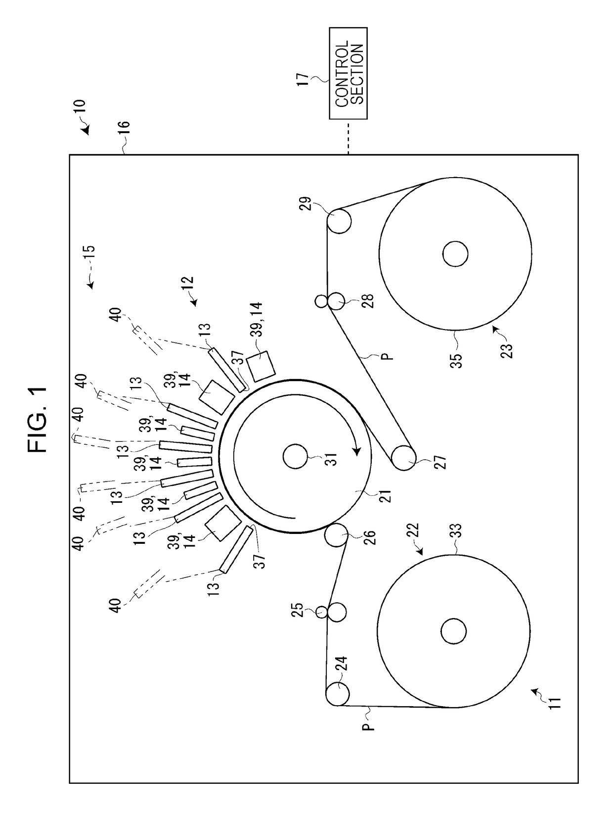
first embodiment
Cleaning Liquid Supplying Apparatus of First Embodiment
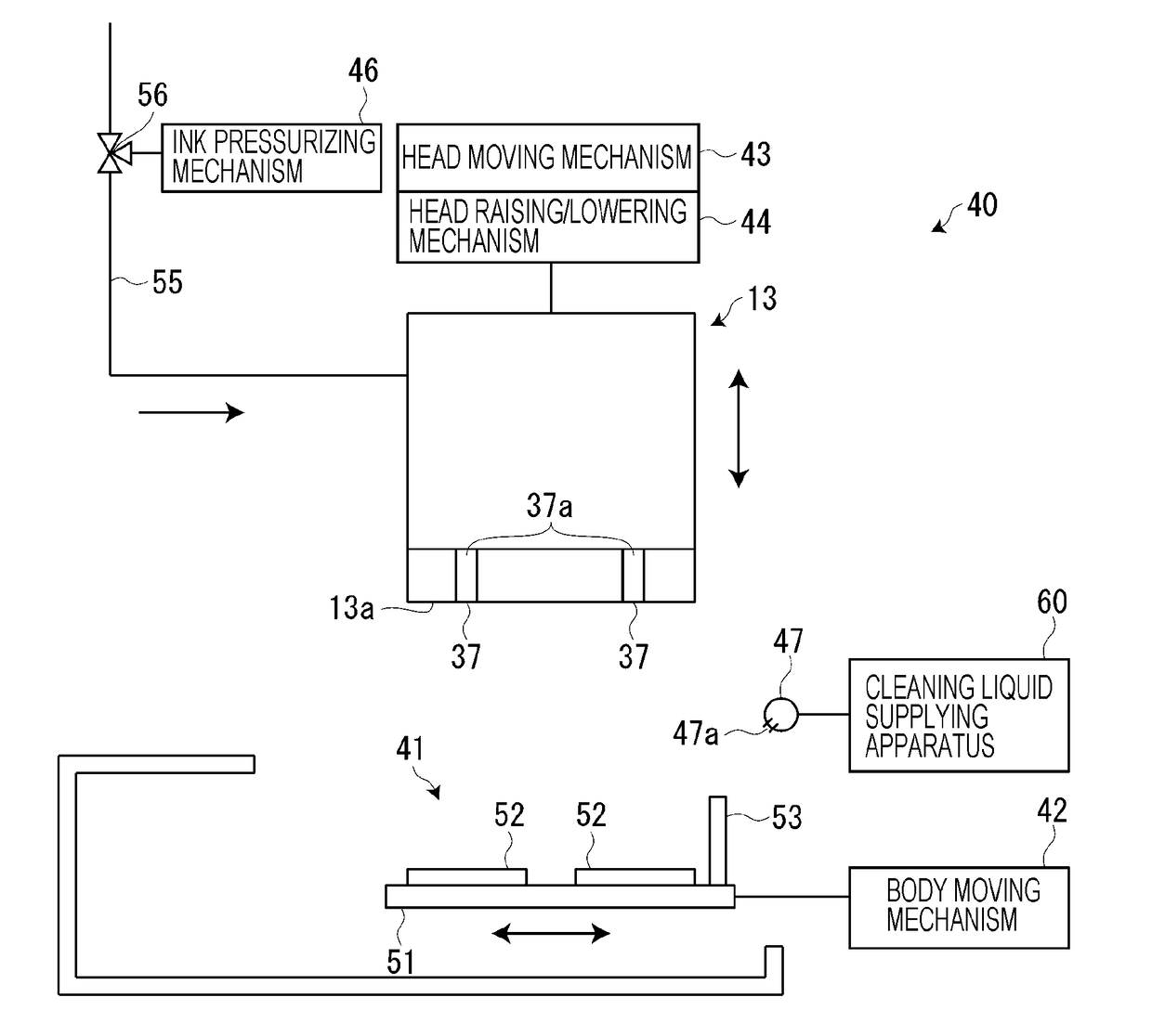
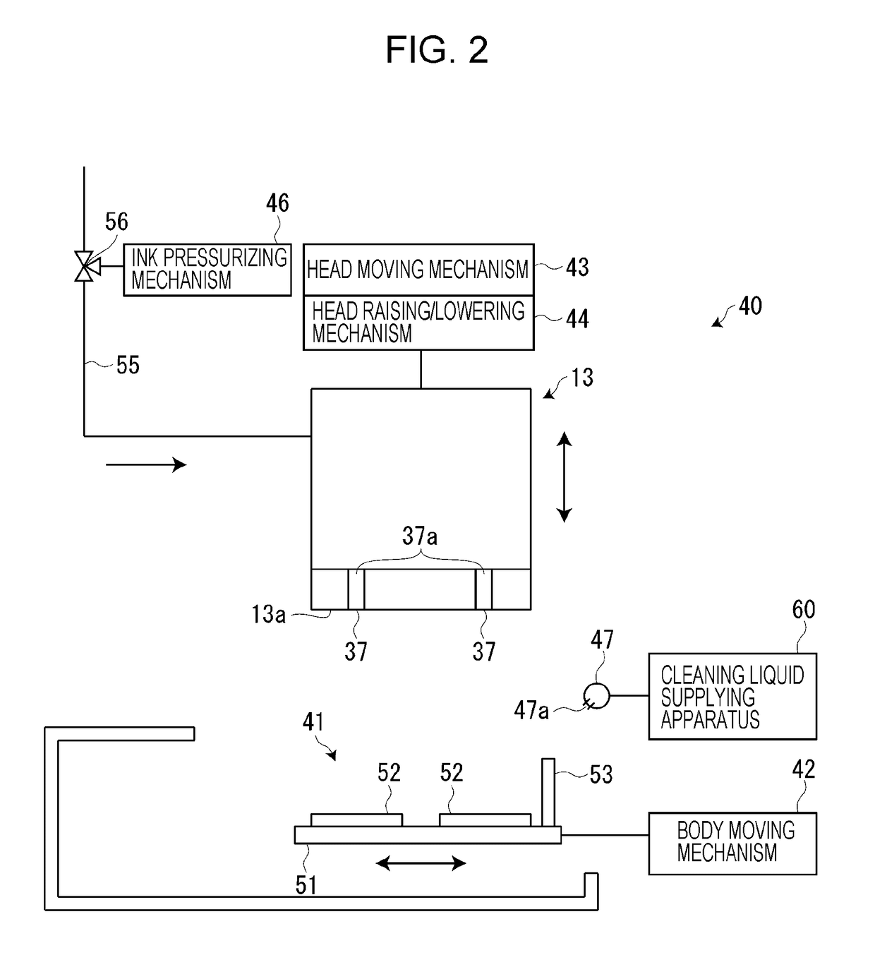
[0062]Next, the cleaning liquid supplying apparatus 60 according to a first embodiment is described with reference to FIG. 4. As described above, the cleaning liquid supplying apparatus 60 supplies cleaning liquid to the six cleaning liquid ejecting sections 47 of the six maintenance units 40.
[0063]As illustrated in FIG. 4, the cleaning liquid supplying apparatus 60 includes a main storage section 61 (first storage section) that stores cleaning liquid, a pressure-accumulating sub-storage section 62 (second storage section) that is connected to the main storage section 61 via a main flow channel 63 (first flow channel), and the six cleaning liquid ejecting sections 47 that are connected to the sub-storage section 62 via six individual flow channels 64. Further, the cleaning liquid supplying apparatus 60 includes a cleaning liquid pump 66 (liquid sending section) that is provided midway along the main flow channel 63 and sends the...
second embodiment
Cleaning Liquid Supplying Apparatus of Second Embodiment
[0072]Next, a cleaning liquid supplying apparatus 60A according to a second embodiment is described with reference to FIG. 5. In this embodiment, differences from the first embodiment are mainly described. As illustrated in FIG. 5, the cleaning liquid supplying apparatus 60A of the second embodiment includes, in addition to the components of the first embodiment, a cleaning liquid returning section 73 that includes a return flow channel 74 and returns the cleaning liquid in the sub-storage section 62 to the main storage section 61, and an atmosphere opening / closing section 75 that includes an air flow channel 76 and opens / closes the air reservoir 62a of the sub-storage section 62 to / from the atmosphere.
[0073]The cleaning liquid returning section 73 includes the return flow channel 74 through which the cleaning liquid in the sub-storage section 62 is returned to the main storage section 61, and a return opening / closing valve 77 ...
third embodiment
Cleaning Liquid Supplying Apparatus of Third Embodiment
[0085]Next, a cleaning liquid supplying apparatus 60B according to a third embodiment is described with reference to FIG. 6. In this embodiment, differences from the first embodiment are mainly described. As illustrated in FIG. 6, in the cleaning liquid supplying apparatus 60B of the third embodiment, a sub-storage section 62B has a structure different from that of the sub-storage section 62 of the first embodiment. In the sub-storage section 62B of the third embodiment, a piston-like member 81 is provided in the air reservoir 62a in a freely ascending / descending fashion. Further, a position detecting section 82 that detects the position of the piston-like member 81 in the ascending / descending direction is provided.
[0086]The piston-like member 81 is formed of a chemical-resistant resin or the like, and includes a piston body 84 and a rod portion 85 extending from the piston body 84. The piston body 84 is provided on the inner pe...
PUM
 Abstract
Description
Claims
Application Information