Catheter

Active Publication Date: 2017-10-05
JAPAN LIFELINE CO LTD
View PDF3 Cites 2 Cited by
  • Summary
  • Abstract
  • Description
  • Claims
  • Application Information

AI Technical Summary

Benefits of technology

The invention is a catheter with a metal ring that helps to accurately measure the temperature of a hollow organ inside the body. The metal ring is embedded into the inner tube of the catheter and is designed to have a thick structure, which reduces the transfer of heat to the surrounding tissues. This allows for accurate temperature readings. However, when making the tip-flexible part of the catheter, the thick metal ring may be difficult to embed into the inner tube. To address this, the metal ring and the divided tube members are both fitted on the inner tube side by side in the axial direction of the catheter tube. This makes it easier to form the tip-flexible part and ensures the accurate measurement of temperature. The metal ring and the plurality of divided tube members may have a flat outer circumferential surface, which reduces the risk of damage to the nasal cavity or the hollow organ and increases the accuracy of the temperature measurement. The catheter may also include a deflection mechanism that allows for easy insertion through complex-structured nasal cavity and esophagus. Overall, the invention simplifies the manufacturing process of the catheter and makes it easier to insert into the body.

Problems solved by technology

However, upon forming the tip-flexible part of the catheter tube, such a thick-structured metal ring may involve difficulties in employing an example method that causes the metal ring to be embedded into the outer circumferential surface of a second tube by striking the metal ring from outside.

Method used


Image

  • Catheter
  • Catheter
  • Catheter

Examples


modification examples

[0094]Although the invention has been described with reference to one embodiment, the invention is not limited to the embodiment but may be modified in a wide variety of ways.

[0095]For example, shapes, locations, materials, etc., of the respective members described in the foregoing embodiment are non-limiting, and may respectively be any other shape, location, material, etc.

[0096]In addition, although the catheter tube 11 has been described with specific reference to the configuration thereof in the foregoing embodiment, it is not necessary for the catheter tube 11 to include all of the components. Alternatively, the catheter tube 11 may be further provided with any other component. In one specific example, the catheter tube 11 may include, as a swinging member, a plate spring provided inside the catheter tube 11 and deformable in a direction of flexure. Factors such as locations, shapes, and the number of metal rings 111 to 115 and the tip 110 of the catheter tube 11 are not limite...


PUM


Abstract

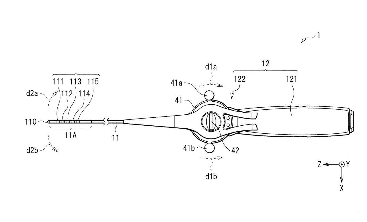
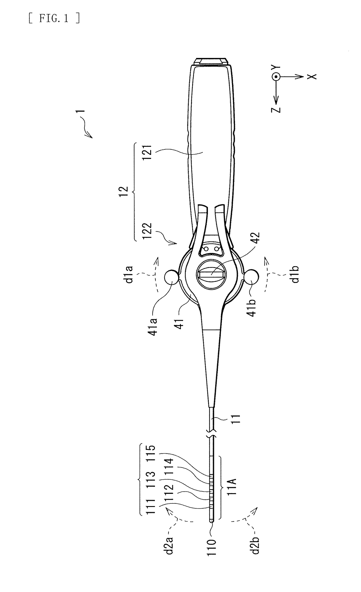
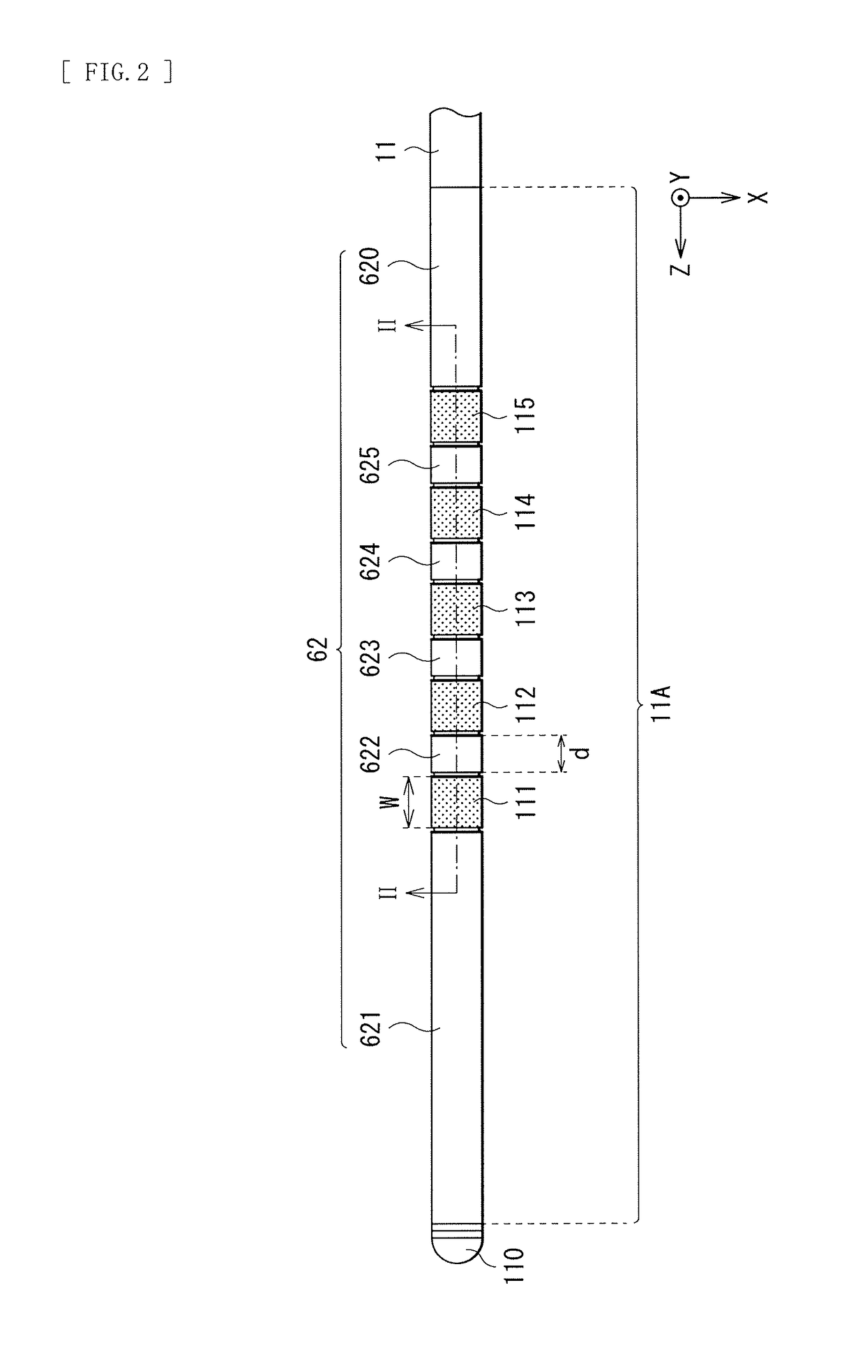
Provided is a catheter that is manufacturable in a simplified fashion. The catheter 1 includes: a catheter tube 11 including a tip-flexible part 11A that has an inner tube (first tube 61) and a plurality of divided tube members 620 to 625 that are disposed on outer circumference of the inner tube and independent of each other; one or a plurality of metal rings disposed in the tip-flexible part 11A; one or a plurality of temperature sensors disposed corresponding to the one or the plurality of metal rings; and a handle 12 attached at a base end of the catheter tube 11. A rate of a thickness of the metal ring to an outer diameter of the metal ring is 7.5% or greater. The metal ring and the plurality of divided tube members 621 to 625 are both so disposed in the tip-flexible part 11A as to be fitted on an outer circumferential surface of the inner tube side by side in an axial direction of the catheter tube 11.

Description

TECHNICAL FIELD[0001]The invention relates to a catheter having a temperature sensor.BACKGROUND ART[0002]An operation that performs cauterization or ā€œablationā€ with use of an ablation catheter has been performed as one of medical treatments for arrhythmia, etc. Such ablation that uses the ablation catheter may be performed on a site that involves the arrhythmia inside the heart, for example. In general, methods of the ablation may be roughly classified into a method that performs heating and a method that performs cooling. More specifically, the methods of the ablation may be roughly classified into a high-temperature ablation that uses a high frequency current and a low-temperature ablation that uses liquid nitrous oxide, liquid nitrogen, etc. When performing the ablation of a site such as the posterior wall of the left atrium of the heart by means of the ablation catheter, i.e., upon surgical ablation of the left atrium, the esophagus located in the vicinity of the posterior wall ...

Claims


Application Information

Patent Timeline
IPC IPC(8): A61B18/14A61B8/12A61N1/05
CPCA61B18/1492A61N1/0517A61B8/445A61M25/008A61B8/12A61B5/01A61B5/6855A61B5/4233A61B2018/00351A61B2018/00488A61B2018/00577A61B2018/00791A61B2018/00797A61B18/12A61M25/0082A61B2562/0271A61B2018/00595A61M2230/50
InventorMASUDA, TAKUYA
OwnerJAPAN LIFELINE CO LTD