Measurement system and method for matching and/or transmission measurements

Active Publication Date: 2020-05-28
ROHDE & SCHWARZ GMBH & CO KG
View PDF2 Cites 1 Cited by
  • Summary
  • Abstract
  • Description
  • Claims
  • Application Information

AI Technical Summary

Benefits of technology

[0026]According to a further preferred implementation form of the first aspect of the invention, the measurement system further comprises a processor for measuring the grade of nulling of the signal of the second receiver signal path. Advantageously, for example, measurement efficiency can further be increased.
[0027]According to a further preferred implementation form of the first aspect of the invention, especially in the case that the at least one signal generator comprises at least two signal generator signal paths, the processor is adapted to sweep phase and/or amplitude difference between the at least two signal generator signal paths and/or the at least two receiver signal paths on the basis of the measured grade of nulling. Advantageously, for instance, measurement accuracy can further be increased.
[0028]According to a further preferred implementation form of the first aspect of the invention, the processor comprises at least one of an application-specific integrated circuit, a digital signal processor, or a field programmable gate array. Advantageously, costs can be reduced, thereby increasing measurement efficiency.
[0029]According to a further preferred implementation form of the first aspect of the invention, the measurement system further comprises a processor for measuring the grade of nulling of the signal in the first receiver signal path. Advantageously, the processor for measu

Problems solved by technology

As it can be seen, due to the complexity of said measurement method and the usage of error-prone processes such as the discrete Fourier transformations,

Method used


Image

  • Measurement system and method for matching and/or transmission measurements
  • Measurement system and method for matching and/or transmission measurements
  • Measurement system and method for matching and/or transmission measurements

Examples


Example

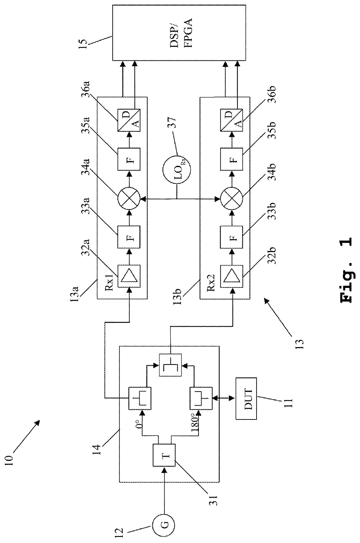
[0039]Firstly, FIG. 1 illustrates an exemplary measurement system for matching and / or transmission measurements with respect to a device under test 11 comprising an interface. Said measurement system10 comprises a signal generator 12 comprising a signal generator signal path, and a receiver 13 comprising two receiver signal paths, especially a first receiver signal path 13a and a second receiver signal path 13b.

[0040]As it can further be seen from FIG. 1, the exemplary measurement system 10 further comprises a resistive measurement bridge 14. Exemplarily, said resistive measurement bridge 14 additionally comprises a balun in the from of a transformer 31 to which the signal generator 12 is connected.

[0041]In this context, the transformer 31 is adapted to realize the directivity of the resistive measurement bridge 14 and to generate the required 0 degree and 180 degrees signals.

[0042]Furthermore, the resistive measurement bridge 14 is not only connected to the interface of the device...


PUM


Abstract

A measurement system for matching and/or transmission measurements with respect to a device under test comprising an interface is provided. Said measurement system comprises at least one signal generator comprising at least one signal generator signal path, and at least one receiver comprising at least two receiver signal paths. In this context, a signal of a first signal generator signal path of the at least one signal generator signal path and/or a signal of a first receiver signal path of the at least two receiver signal paths is adaptively phase-shifted and/or amplitude-modified with respect to a signal of a second receiver signal path of the at least two receiver signal paths.

Description

TECHNICAL FIELD[0001]The invention relates to a measurement system and a corresponding measurement method for matching and / or transmission measurements with respect to a device under test, especially a radio frequency device under test, comprising an interface.BACKGROUND ART[0002]Generally, in times of an increasing number of applications employing a plurality of electrical circuits, especially radio frequency circuitry, there is a growing need of a measurement system and a corresponding measurement method especially for verifying correct functioning of said applications in a highly efficient and accurate manner with special respect to matching and transmission measurements.[0003]U.S. Pat. No. 3,903,477 discloses a measurement method in which the forward and backward scattered energy of a high frequency network or composition of matter exposed to a composite electromagnetic energy wave is sampled by a compensated sampling system and the incident wave and reflected and transmitted re...

Claims


Application Information

Patent Timeline
IPC IPC(8): G01R27/04G01R27/28
CPCG01R27/04G01R27/28G01R29/0892G01R31/2822
Inventor BLOSS, MARTINMAIER, THOMAS
Owner ROHDE & SCHWARZ GMBH & CO KG
Why Eureka
Try Eureka