Electric motor driven pump

Pending Publication Date: 2019-10-31
GRUNDFOS HLDG
View PDF5 Cites 0 Cited by
  • Summary
  • Abstract
  • Description
  • Claims
  • Application Information

AI Technical Summary

Benefits of technology

[0018]It is particularly advantageous if the control electronics of the pump are configured to adapt the amplification of the sensor signal in accordance with the set measurement range. The adaptation is advantageously effected in a manner such that the set measurement range is utilized as completely as possible. If for example a pressure sensor, whose sensor element is configured for a measurement range of 0 to 10 bar, is set by the control electronics to a measurement range of 0 to 2 bar, then it is useful to adapt the amplification of the sensor signal such that a sensor signal as would otherwise be the case at 10 bar, already arises at 2 bar. The measuring accuracy in the set measuring range can be increased by way of this.
[0019]In an analogous manner, it is

Problems solved by technology

The latter is often difficult due to the fact that only a rough estimation is possible before starting operation, and a dimensional adaptation of the sensor devices which is actually necessary, is often not effected at later stage for reasons of cost.
In practice, this leads to sensors with a much too large measurement range often being selected, with the consequence that they lack the necessary acc

Method used


Image

  • Electric motor driven pump
  • Electric motor driven pump
  • Electric motor driven pump

Examples


Example

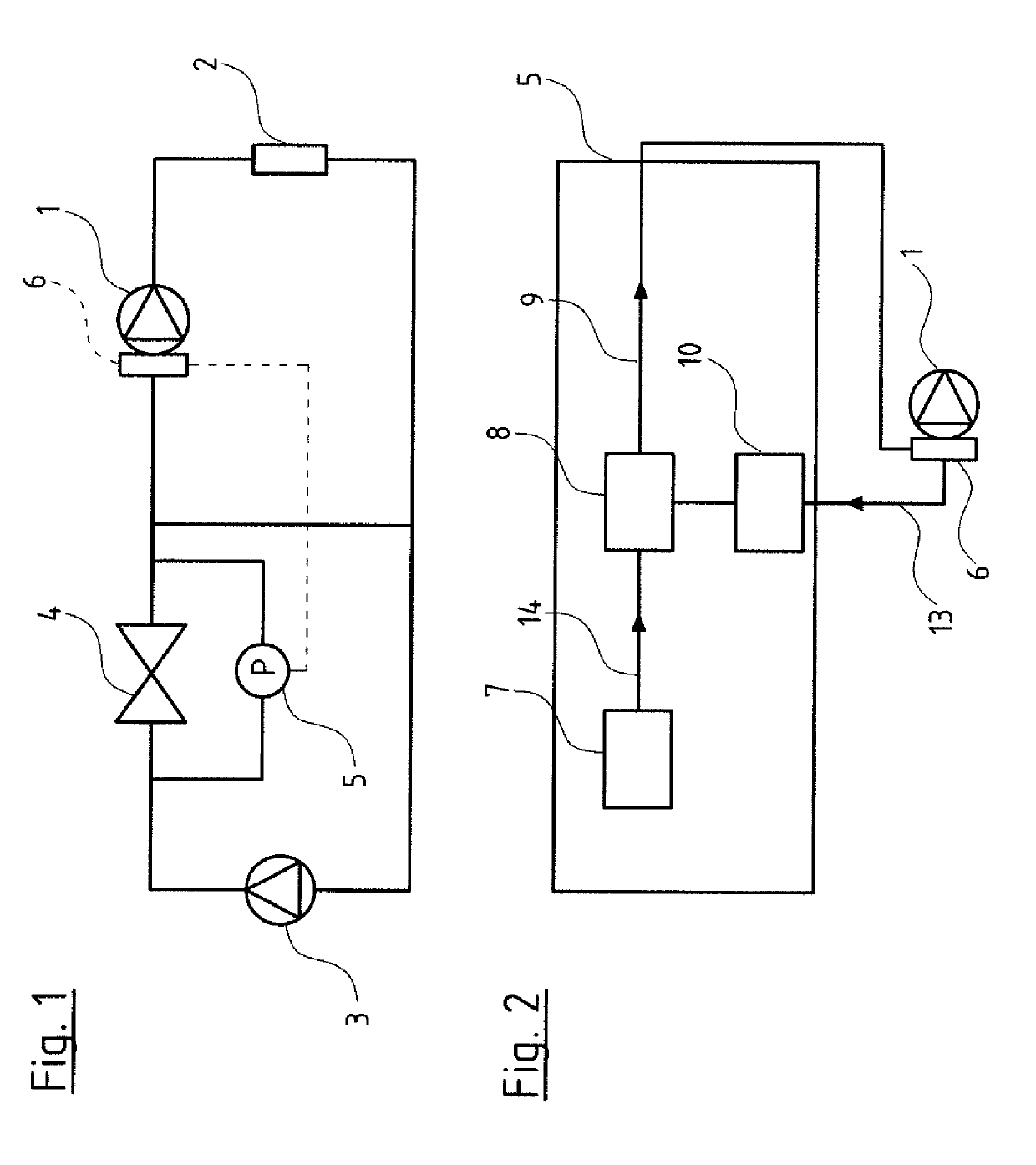
[0034]Referring to the drawings, FIG. 1 by way of example shows a hydraulic circuit, with a first pump 1 which delivers to a consumer 2, whose exit is connected to the entry of the pump 1 as well as to the entry of a second pump 3, at the exit of which second pump a valve 4 connects, said valve connecting the exit of the second pump 3 to the entry of the first pump 1.

[0035]A pressure sensor 5 is arranged parallel to the valve 4. This pressure sensor 5 is a differential pressure sensor which detects the pressure drop at the valve 4. The sensor 5 is connected to control electronics 6 of the pump 1 which form part of frequency converter electronics of an electric motor driving the centrifugal pump 1.

[0036]The control electronics 6 are configured on the one hand to recognize the connected pressure sensor 5 as a pressure sensor and on the other hand to set the measurement range of this pressure sensor 5, as is described further below. The electrical signal of the pressure sensor 5 corres...


PUM


Abstract

An electromotorically driven pump (1) includes control electronics (6) for the connection of at least one sensor (5). The control electronics (6) are configured to detect values of an output signal (9) of the connected sensor (5) continuously or in temporal intervals, and after completion of a predefined time, to automatically set a measurement range of the sensor (5) based on the detected values.

Description

CROSS REFERENCE TO RELATED APPLICATIONS[0001]This application is a United States National Phase Application of International Application PCT / EP2017 / 083018 filed Dec. 15, 2017, and claims the benefit of priority under 35 U.S.C. § 119 of European Application 16205701.2, filed Dec. 21, 2016, the entire contents of which are incorporated herein by reference.TECHNICAL FIELD[0002]The invention relates to an electromotorically driven pump with control electronics which are provided for the connection of at least one sensor.TECHNICAL BACKGROUND[0003]Pumps of this type and which are provided with control electronics typically comprise a frequency converter which renders it possible to adapt operating points of the pump in an almost arbitrary manner within a defined power spectrum. For this, a differential pressure sensor for example is provided on the part of the pump. It is particularly with pump systems as well as pumps of a larger construction type, that it is counted as belonging to the ...

Claims


Application Information

Patent Timeline
IPC IPC(8): F04D15/00F04D13/06G01D1/12G01D3/024
CPCG01D1/12G01D3/024F04D15/00F04D13/06F04D15/0088G01D21/00G01L27/00G01K15/00G01D18/002
Inventor AARESTRUP, JAN CARØEMIKKELSEN, ANDERS SILKÆRCHRISTENSEN, CARSTENMØLGAARD MØLLER, SIMONNIELSEN, RASMUS ØRNDRUP
Owner GRUNDFOS HLDG
Why Eureka
Try Eureka