
Orchestrated energy

a technology of orchestrated energy and energy storage, applied in the direction of emergency power supply arrangements, instruments, computer control, etc., can solve the problems of inability to receive advance notice of shutoff, inability to meet the needs of customers, and inability to coordinate between the needs of customers and utilities,

Active Publication Date: 2017-10-05
TENDRIL OE LLC
View PDF3 Cites 26 Cited by
  • Summary
  • Abstract
  • Description
  • Claims
  • Application Information

AI Technical Summary

Benefits of technology

The patent describes a facility that helps manage and optimize energy consumption and production in buildings and other energy systems. It uses advanced techniques to control and use energy systems more efficiently, reducing costs and improving comfort. The facility takes into account various constraints, such as user preferences, environmental factors, and financial considerations, to achieve the best results. It can also be used for individual devices, multiple controllable devices, and larger systems comprising multiple buildings. Overall, the facility provides a better solution for managing and optimizing energy systems.

Problems solved by technology

Although there have been many attempts to improve energy conservation and reduce energy costs, these attempts do not typically satisfy the demands or goals of customers and / or utilizes or coordinate between the goals of those customers and utilities.
However, end-users may not receive advance notice of the shutoff and may find themselves uncomfortable at inopportune times. As another example, a user can use a thermostat to create a temperature schedule for a building so that the user remains comfortable while occupying the building.
However, the schedules may not take into account the cost of energy, thereby ignoring any potential for cost savings to the user, the utility, or both in a market that can have volatile pricing.
Furthermore, while the “Internet of Things” has created a wealth of sensors and other devices within various energy systems to measure both the energy consumption of the system and the environment within which the system operates, these sensors do not often communicate effectively.

Method used

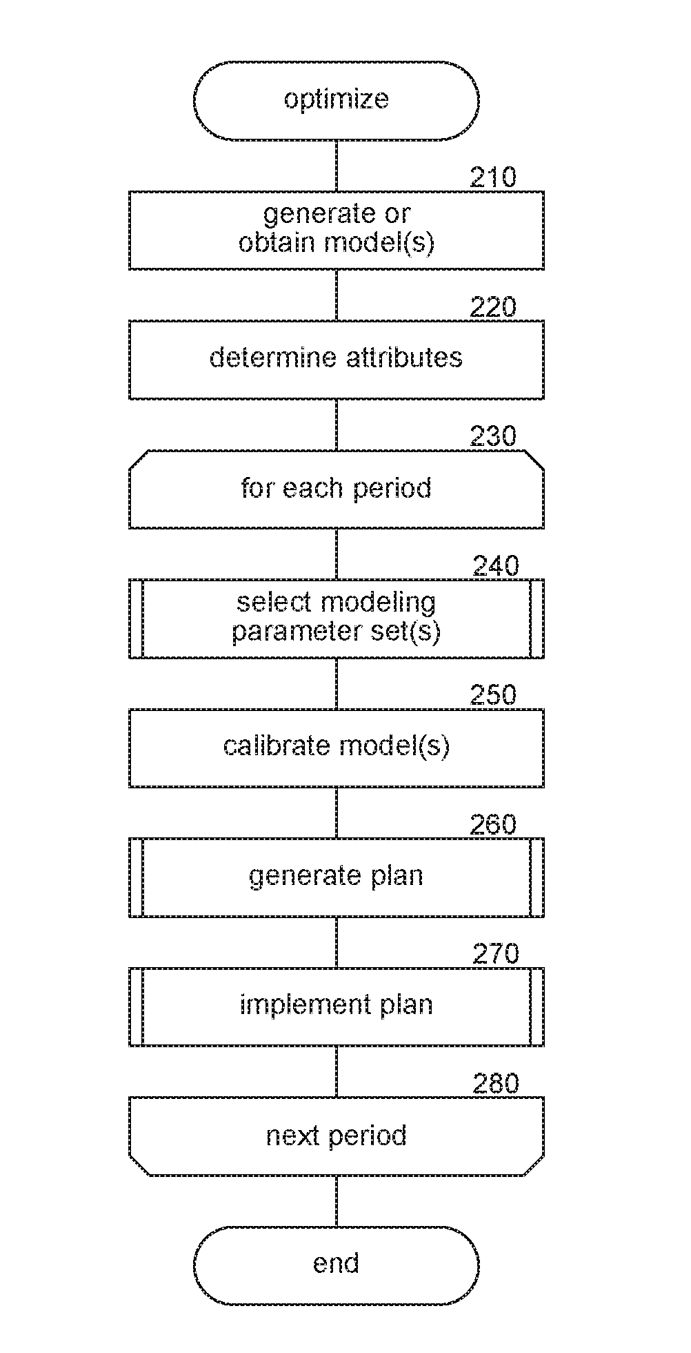

Image

  • Orchestrated energy
  • Orchestrated energy
  • Orchestrated energy

Examples


Embodiment Construction

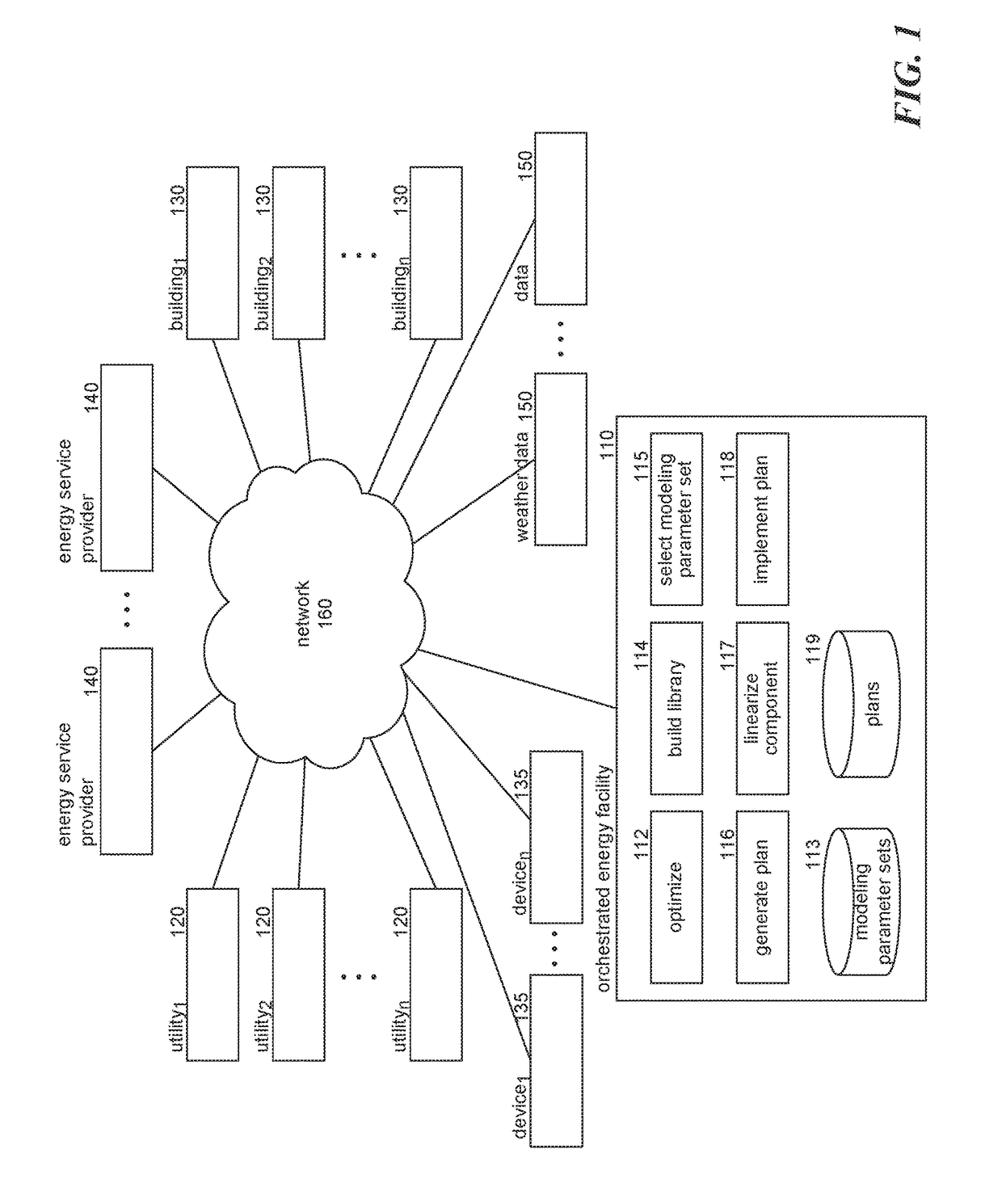
[0011]A facility providing systems and methods for managing and optimizing energy consumption and / or production is provided. The facility provides techniques for optimizing energy-consuming and energy-producing systems (“energy systems”) to meet specified demands or goals, such as reducing load, reducing cost, increasing usage of specific types of energy sources (e.g., solar or wind), reducing usage of specific types of energy sources (e.g., coal or hydroelectric), increasing comfort within a building, and so on in accordance with various time-dependent constraints (e.g., a user's temperature comfort band during certain times of day, willingness to use energy provided by various sources (e.g., nuclear) during certain times of year). The demands, goals, and / or constraints may be specified by a resident or owner of one or more energy systems, a building, a utility, an energy service provider, and so on. For example, the facility may reduce the cost of energy (a goal) by shifting loads...


PUM


Abstract

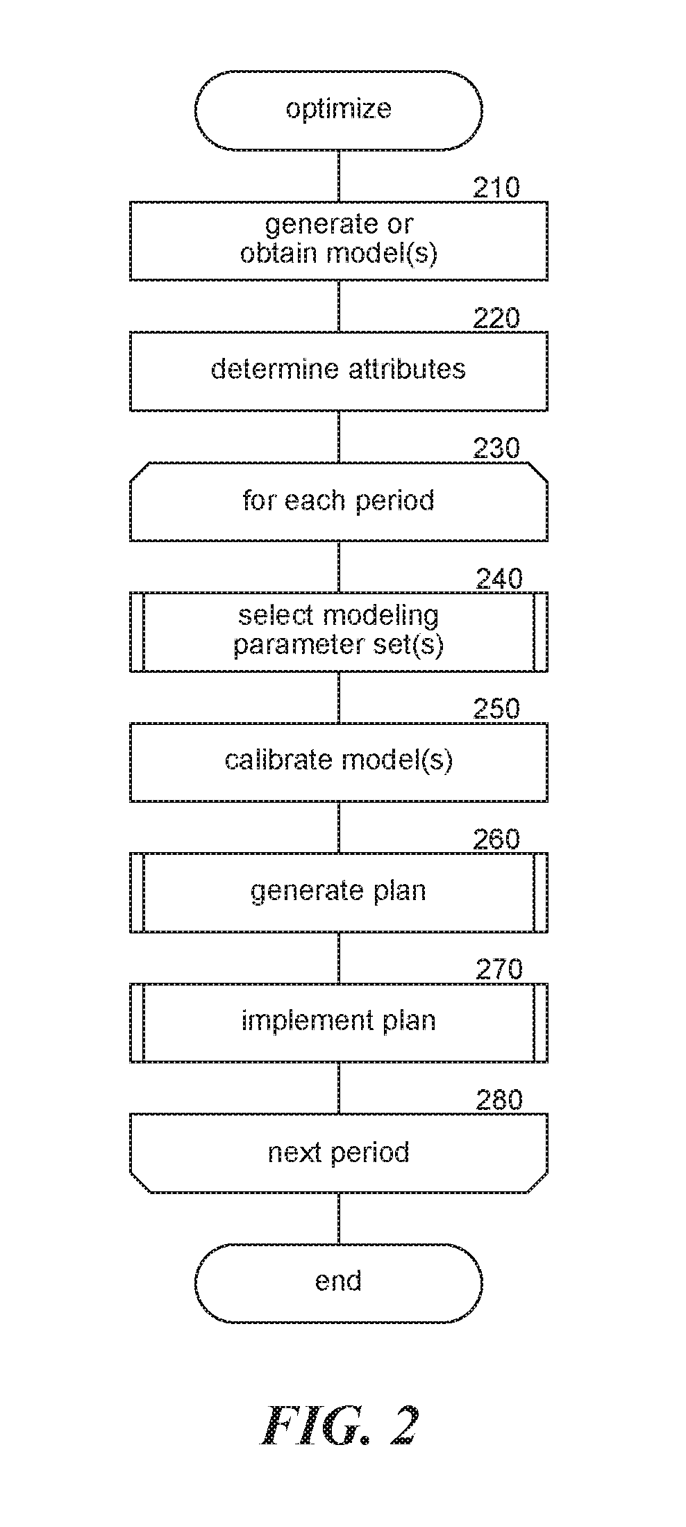
A facility providing systems and methods for managing and optimizing energy consumption and / or production is provided. The facility provides techniques for optimizing energy-consuming and energy-producing systems to meet specified demands or goals in accordance with various constraints. The facility relies on models to generate an optimization for an energy system. In order to use generic models to simulate and optimize energy consumption for an energy system, the generic models are calibrated to properly represent or approximate conditions of the energy system during the optimization period. After the appropriate models have been calibrated for a given situation using one or more modeling parameter sets, the facility can simulate inputs and responses for the corresponding system. The facility uses the generated simulations to generate a plan or control schedule to be implemented by the energy system during the optimization period.

Description

RELATED APPLICATIONS[0001]This application claims the benefit of U.S. Provisional Application No. 62 / 317,426, entitled ORCHESTRATED ENERGY, filed on Apr. 1, 2016, which is herein incorporated by reference in its entirety. In cases where the present application and a document incorporated herein by reference conflict, the present application controls.BACKGROUND[0002]As energy resources become scarcer, and as people become more environmentally conscious, their desire optimize energy consumption and reduces costs has increased. Although there have been many attempts to improve energy conservation and reduce energy costs, these attempts do not typically satisfy the demands or goals of customers and / or utilizes or coordinate between the goals of those customers and utilities. For example, demand management systems (direct load control systems) enable utilities to essentially turn off end-user devices (e.g., air conditioning units) when demand peaks to, for example, avoid blackouts or rol...

Claims


Application Information

Patent Timeline
IPC IPC(8): H02J3/00H02J9/00
CPCH02J3/005H02J9/002H02J2003/003H02J2003/001H02J9/005G05B15/02G06Q10/04H02J3/003H02J2203/20Y02E60/00Y04S40/20Y04S10/50Y02E40/70
Inventor HUMMON, MARISSABLACK, CHRISMEIER, JAKESULLIVAN, PATRICKFELDMAN, BRETT
Owner TENDRIL OE LLC
Learn More