Device for Processing Harvested Crops and Method for Controlling the Flow of a Harvested Crop in the Device

a technology for harvesting equipment and harvesting crops, applied in baling, agriculture, agricultural tools and machines, etc., can solve the problems of increased grain loss, loss of apparatus efficiency, and loss of mass needed for breaking down, and achieve no loss of apparatus efficiency and grain loss reduction

Inactive Publication Date: 2017-10-12
KEMMNER HARTMUT
View PDF7 Cites 5 Cited by
  • Summary
  • Abstract
  • Description
  • Claims
  • Application Information

AI Technical Summary

Benefits of technology

The patent describes a device for reducing grain loss during the harvesting process. The device has a control element that narrows the passage region as it moves in, which causes the crop to slow down and reduces the chance of grain loss. This method also helps to increase the overall mass of the harvested crop and minimize efficiency losses. The control element is adjusted based on the operating situation to ensure the crop flows are optimized. Overall, this device improves the efficiency and reduces the loss of grain during the harvesting process.

Problems solved by technology

A disadvantage of this method is that, specifically in the case of harvested crops having a relatively high grain portion and little other plant constituents, increased grain losses occur since the overall mass which is necessary for breaking down the grains by abrasion is too low.
Due to the overall mass being too low, the grains are only partially broken off by abrasion, or the separating surfaces of the apparatus are only partially charged with harvested crop.
If the threshing gap between the rotor and the threshing concave is greatly reduced in order to reduce the grain losses, this leads to losses in efficiency of the apparatus.
In other words, the achievable harvesting efficiency is therefore reduced.
In the case of known threshing or separating apparatuses, increased grain losses and / or losses of efficiency occur in particular at the beginning and at the end of each threshing operation (for example when turning the combine harvester around at the end of the field) since the threshing and / or separating apparatus is virtually completely emptied in this operating situation and therefore the overall mass of the harvested crop is insufficient for efficiently breaking down the grains by abrasion.
This problem is reinforced in the case of harvested crops which have very low amounts of plant constituents.

Method used


Image

  • Device for Processing Harvested Crops and Method for Controlling the Flow of a Harvested Crop in the Device
  • Device for Processing Harvested Crops and Method for Controlling the Flow of a Harvested Crop in the Device
  • Device for Processing Harvested Crops and Method for Controlling the Flow of a Harvested Crop in the Device

Examples


Embodiment Construction

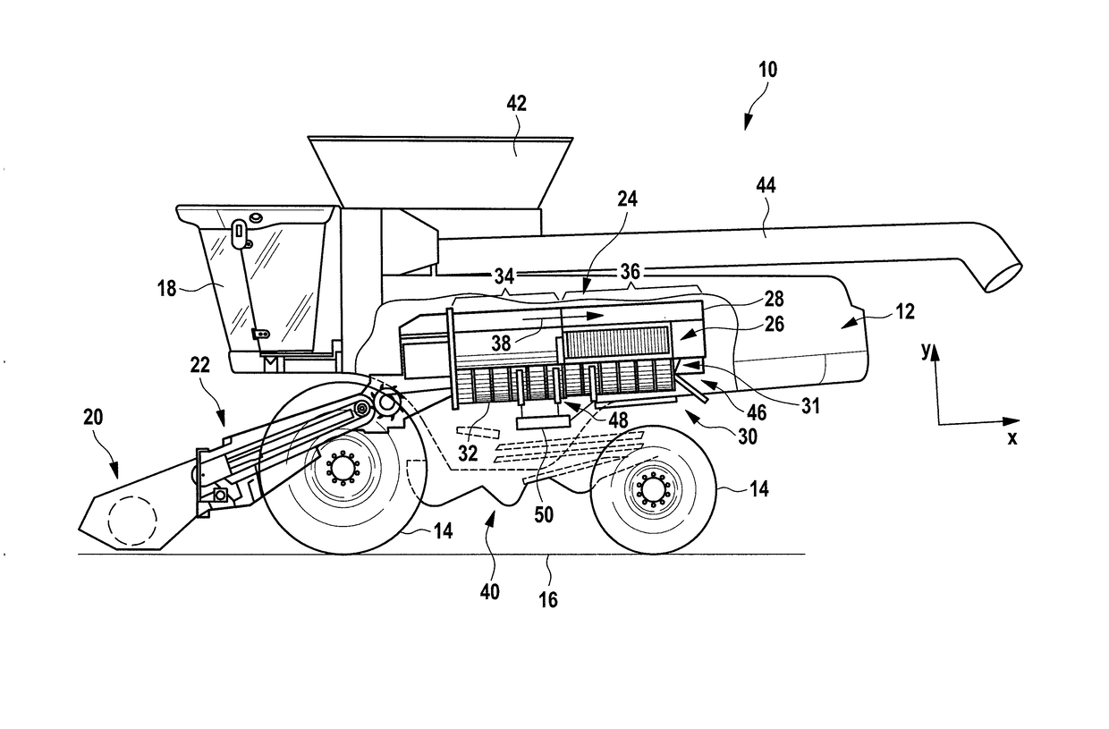
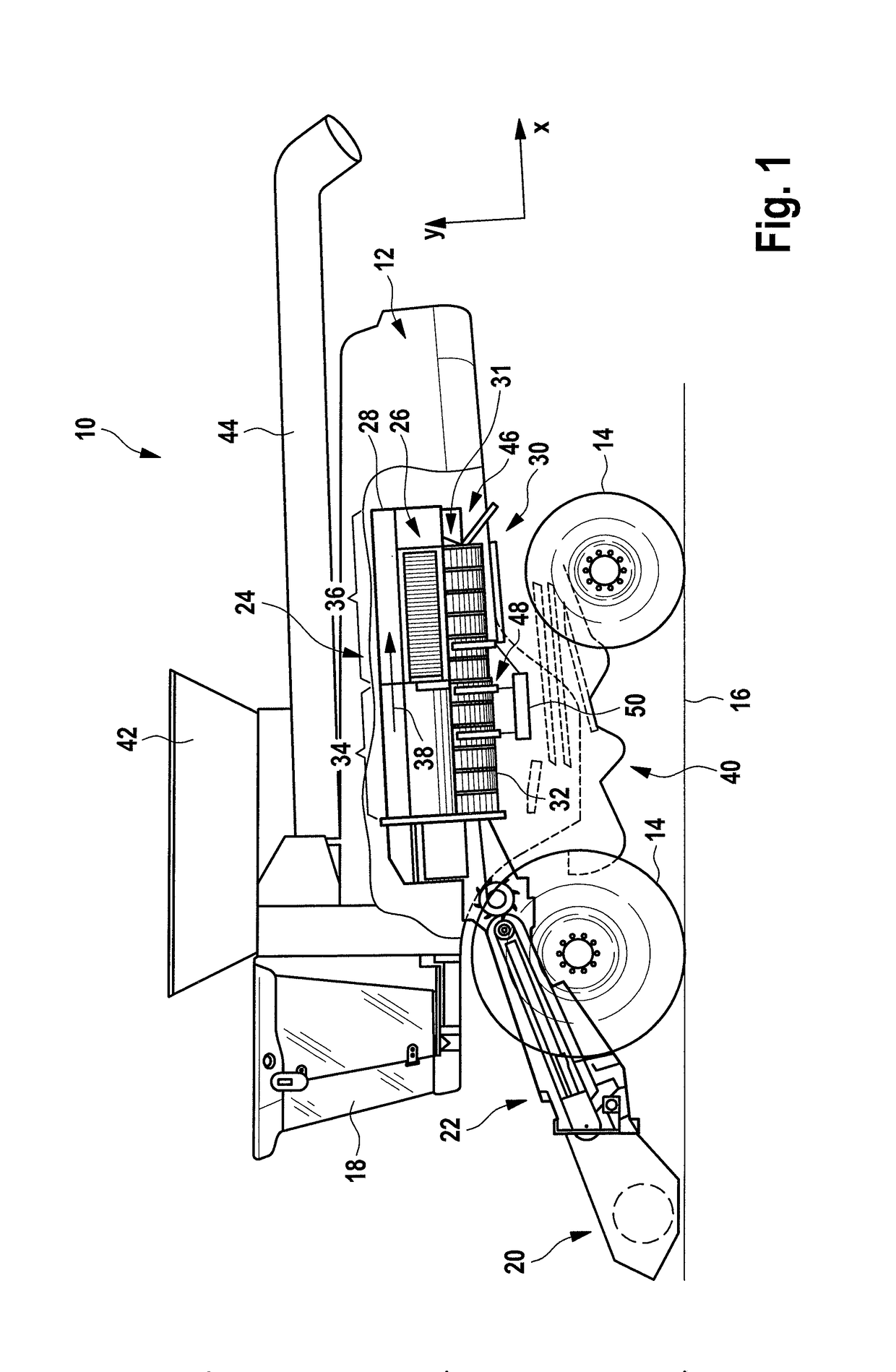
[0064]In FIG. 1, the combine harvester is denoted in general by 10.

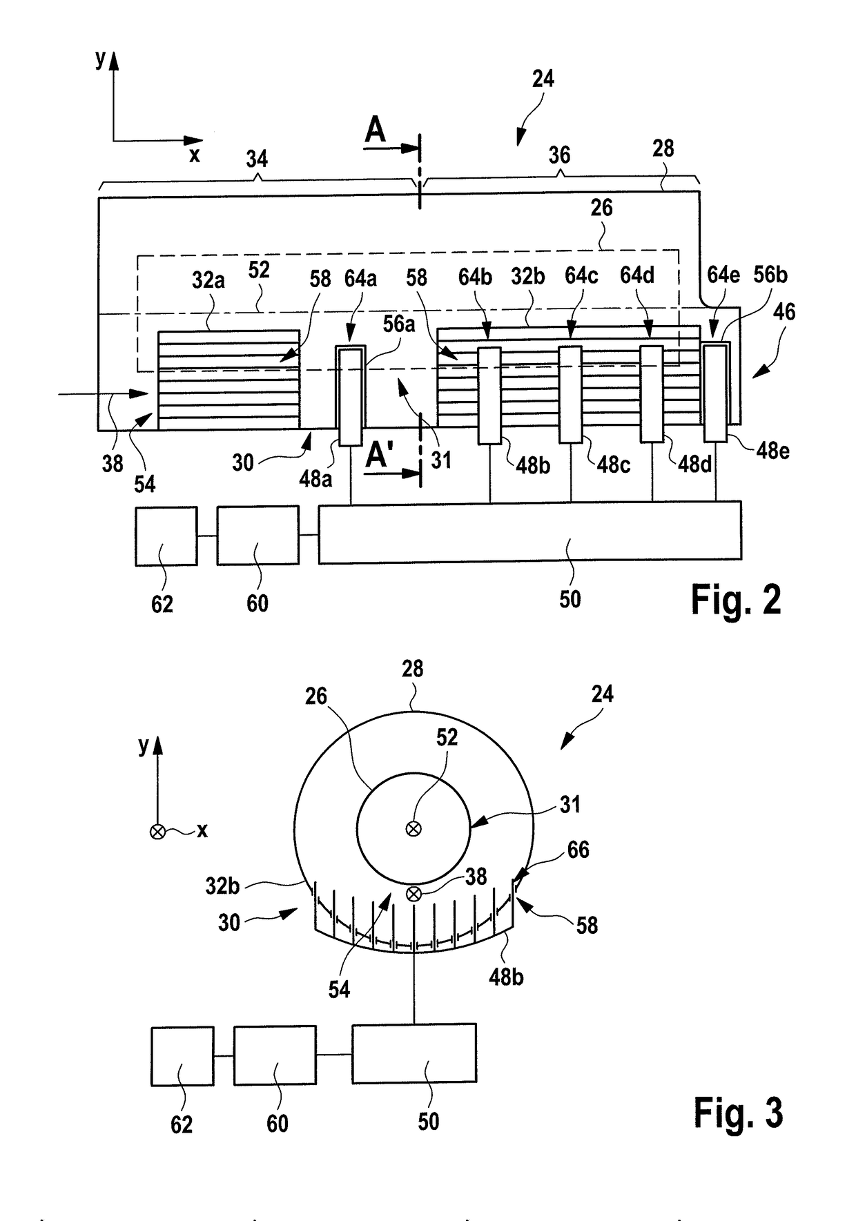
[0065]The combine harvester 10 has a supporting structure 12 and wheels 14 which are in engagement with an underlying surface 16. Furthermore, the combine harvester 10 has a driver's cab 18 from which a driver operates the combine harvester 10. A cutting mechanism 20 of the combine harvester 10 is used to harvest harvested crop containing grain and to supply the harvested crop to an inclined conveyor 22. The harvested material is supplied to an apparatus 24 with the aid of the inclined conveyor 22. In the present exemplary embodiment, the apparatus 24 forms a threshing and separating apparatus which serves to sever the grain from the remaining plant constituents of the harvested crop. The apparatus 24 here has a rotor 26 and a separating device 28 which surrounds the rotor 26 at a radial distance. In particular, the separating device 28 has a separating device region 30 which at least partially surrounds a lower circ...


PUM


Abstract

An apparatus for processing harvested crops, in particular a threshing and / or separating apparatus, comprising a rotor which is mounted rotatably about its longitudinal axis, a separating device with a separating device region which at least partially surrounds a lower circumferential region of the rotor, the circumferential region being arranged below the longitudinal axis in an operationally ready state of the apparatus, and is arranged radially spaced apart from the rotor. A passage region for the harvested crop is formed between the separating device regions and the lower circumferential region of the rotor, wherein the separating device region extends along the longitudinal axis, and comprises at least one control element. The control element is movable into the passage region and / or into an axial projection of the passage, in order to control the flow of harvested crop.

Description

[0001]This application claims the priority of German patent application DE 10 2014 114 717.0, filed on Oct. 10, 2014. The entire content of this application is herewith incorporated by reference.FIELD[0002]The invention generally relates to an apparatus for processing harvested crops, such as a threshing and / or separating apparatus, comprising a rotor which is mounted rotatably about its longitudinal axis, and a separating device with a separating device region which at least partially surrounds a lower circumferential region of the rotor, said circumferential region being arranged below the longitudinal axis in an operationally ready state of the apparatus, and is arranged radially spaced apart from the rotor, wherein a passage region for the harvested crop is formed between the separating device region and the lower circumferential region of the rotor, and wherein the separating device region extends along the longitudinal axis, at least in a partial region of the rotor.[0003]The ...

Claims


Application Information

Patent Timeline
IPC IPC(8): A01D41/127A01F17/02A01F15/10A01D87/02
CPCA01D41/127A01D87/02A01D91/00A01F15/10A01D61/00A01F17/02A01F7/067A01F12/28
Inventor KEMMNER, HARTMUT
Owner KEMMNER HARTMUT
Why Eureka
Try Eureka