
Visual field measuring device and system

a measuring device and visual field technology, applied in the field of visual field measuring devices and systems, can solve the problems of requiring skilled personnel to operate, requiring a lot of space, and requiring a lot of space, and achieve the effect of comparatively compact and inexpensive, and simple operation

Active Publication Date: 2017-10-12
CARL ZEISS MEDITEC AG +1
View PDF4 Cites 9 Cited by
  • Summary
  • Abstract
  • Description
  • Claims
  • Application Information

AI Technical Summary

Benefits of technology

The invention provides devices for measuring the visual field that are small and cheap. The devices can be easily operated by users. The program code, when executed on a processor, can activate the display to show light stimuli for visual field measurement. The program can also display images for the left and right eye on different parts of the display. The invention allows for the use of existing mobile computer devices, such as smartphones or tablets, for perimetry measurement. This makes the device more affordable and easier to use.

Problems solved by technology

Such conventional perimeters require a lot of space, are comparatively expensive, and / or require skilled personnel to operate them.

Method used


Image

  • Visual field measuring device and system
  • Visual field measuring device and system
  • Visual field measuring device and system

Examples


Embodiment Construction

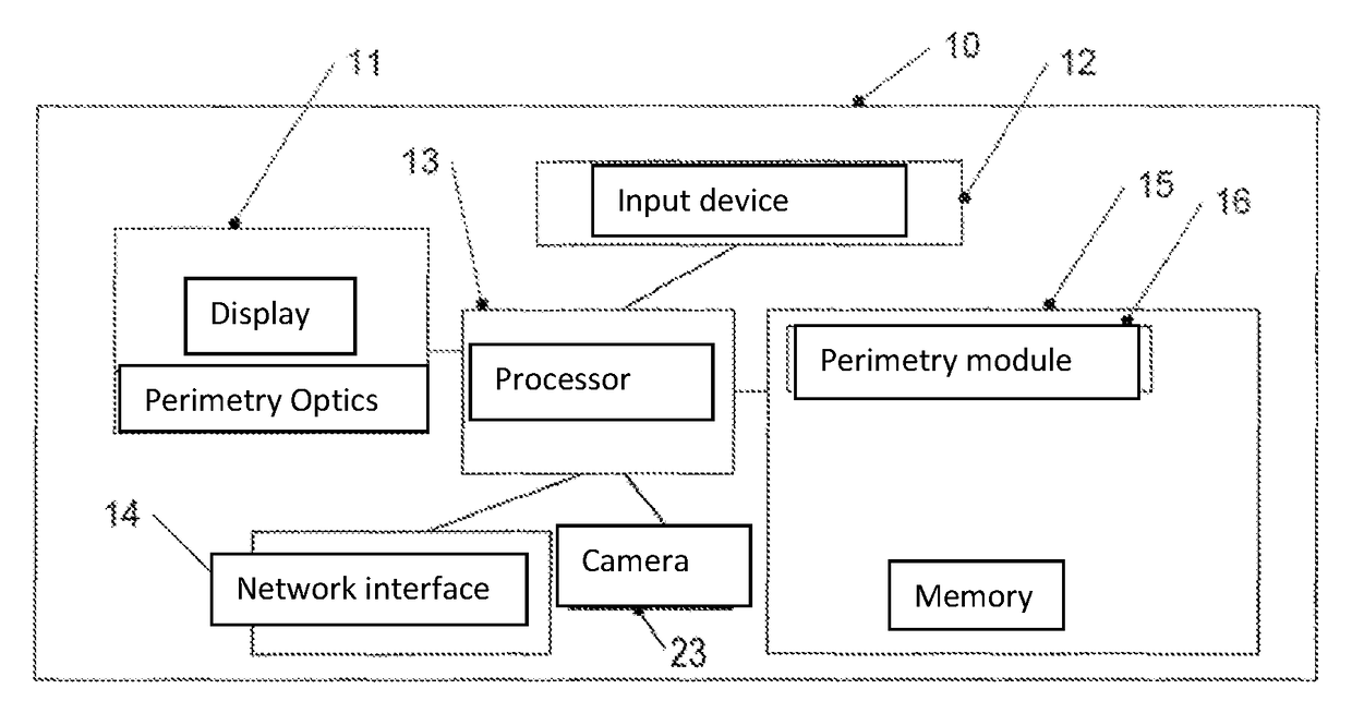
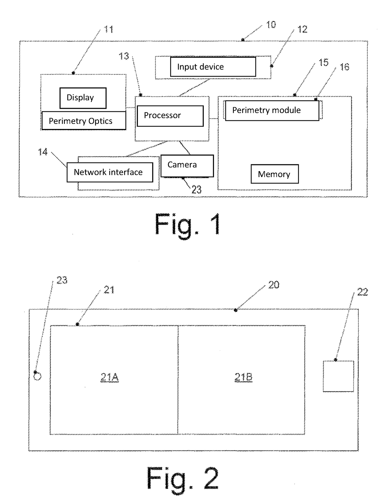
[0056]FIG. 1 shows a mobile computer device 10 according to an example embodiment. The mobile computer device 10 may be implemented by use of a Smartphone, a tablet computer, or by use of another mobile computer device (such as a mobile game device), for example. Such mobile computer devices, which can serve as the basis for the implementation of the mobile computer device 10 of FIG. 1, are often freely programmable, have a processor, a display (display possibly touch-sensitive), different input devices, network interfaces, etc. As is clarified below, such mobile computer devices are used in example embodiments of the present invention to provide diagnostic possibilities to measure a visual field (perimetry). In particular, the mobile computer device can be programmed here accordingly, for example by use of one or several so-called apps (from the English “applications”, meaning user programs).

[0057]As an example, the mobile computer device of FIG. 1 comprises a processor 13, for ins...


PUM


Abstract

The invention relates to mobile computer devices, front-mounted optical systems and computer program products allowing perimetry measurement.

Description

RELATED APPLICATIONS[0001]The present application is a National Phase entry of PCT Application No. PCT / EP2015 / 071726, filed Sep. 22, 2015, which claims priority from DE Patent Application No. 10 2014 113 682.9, filed Sep. 22, 2014, said applications being hereby incorporated by reference herein in their entirety.FIELD OF THE INVENTION[0002]The present application concerns a device for the measurement of the visual field (perimetry), an optical attachment for this purpose and a corresponding computer program product.BACKGROUND[0003]Perimetry is a procedure to examine a visual field of a person. The visual field of a single eye thereby extends towards the temple up to approx. 90 degrees, towards the nose and upwards to about 60 degrees and downwards to about 70 degrees. The different expansion is provided by the protected location of the eye in the eye socket. Towards the nose, the nasal bridge restricts the visual field, upwards and downwards the orbital margin, while the side of the...

Claims


Application Information

Patent Timeline
Patent Type & Authority Applications(United States)
IPC IPC(8): A61B3/024A61B3/00
CPCA61B3/0033A61B3/024
Inventor CORRENS, NICODOBSCHAL, HANS-JURGENMACHALETT, ELKE
Owner CARL ZEISS MEDITEC AG
Learn More