
Left atrial appendage occlusion device delivery system

a technology of appendage occlusion and delivery system, which is applied in the field of medical devices and delivery systems, can solve the problems of ischemic stroke, blood clotting in the appendage, and difficulty in delivering a left atrial appendage occlusion devi

Active Publication Date: 2017-10-12
FLOW MEDTECH
View PDF4 Cites 10 Cited by
  • Summary
  • Abstract
  • Description
  • Claims
  • Application Information

AI Technical Summary

Benefits of technology

The patent describes a system and method for delivering a medical device to bodily orifices. The system includes a cylindrical core cannula with a locking member and one or more expandable members that expand from a compressed position to an expanded position. The system also includes an injection apparatus for transmitting fluid into the device to expand it. The system is detachably connected to the device and is threaded through a hollow access sheath to deliver it to the area of implant. The technical effect of the invention is to provide a reliable and efficient system for delivering medical devices to bodily orifices.

Problems solved by technology

This leads to blood clotting in the appendage, which then becomes a risk as the irregular contraction of the LAA may force the clot to travel out of the appendage and into the brain, leading to an ischemic stroke.
Some patients elect to not take OACs or are ineligible due to side effects.
Delivering a left atrial appendage occlusion device may be challenging due to varying LAA morphologies.
Thus, flush deployment of an LAA occlusion device may not easily be achieved.

Method used


Image

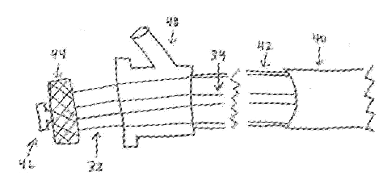
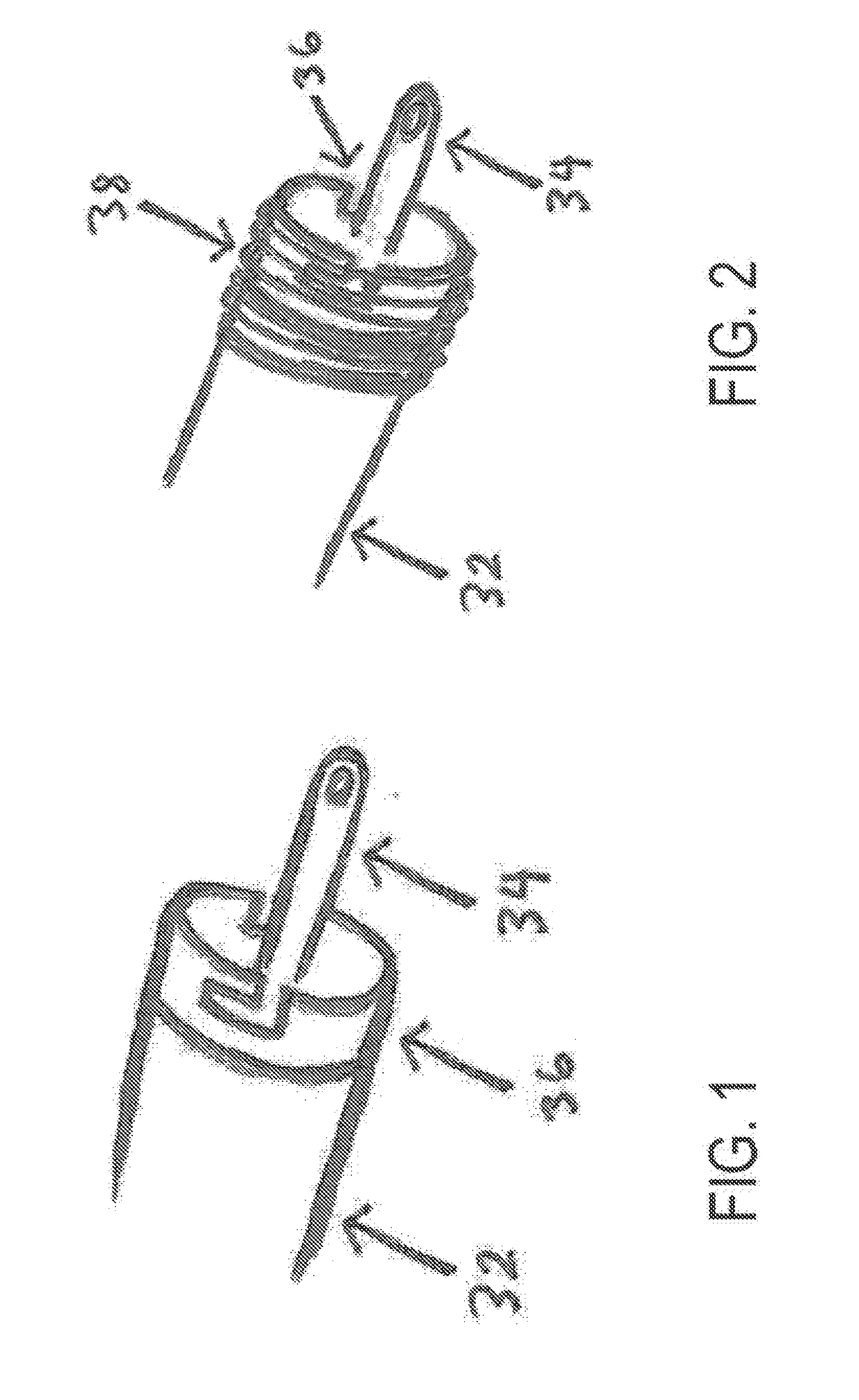
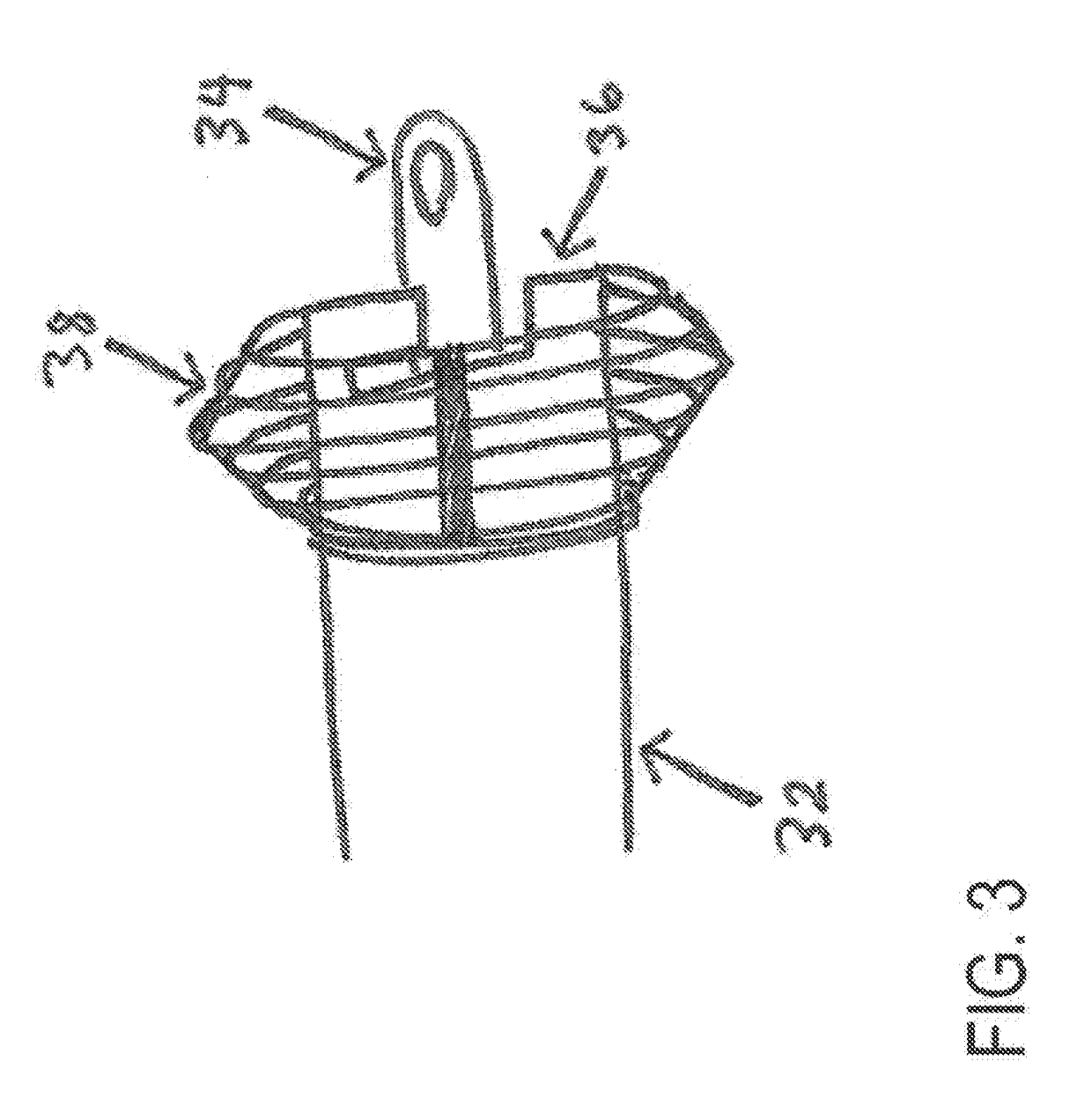
  • Left atrial appendage occlusion device delivery system
  • Left atrial appendage occlusion device delivery system
  • Left atrial appendage occlusion device delivery system

Examples


Embodiment Construction

[0026]Whether or not a term is capitalized is not considered definitive or limiting of the meaning of a term. As used in this document, a capitalized term shall have the same meaning as an uncapitalized term, unless the context of the usage specifically indicates that a more restrictive meaning for the capitalized term is intended. However, the capitalization or lack thereof within the remainder of this document is not intended to be necessarily limiting unless the context clearly indicates that such limitation is intended.

[0027]For the purpose of promoting an understanding of the principles of the present disclosure, reference will now be made to the embodiments illustrated in the figures and specific language will be used to describe the same. It will, nevertheless, be understood that no limitation of the scope of the disclosure is thereby intended; any alterations and further modifications of the described or illustrated embodiments, and any further applications of the principles...


PUM


Abstract

In various embodiments, a system for delivering an implantable device inside a body cavity includes: 1) a core cannula; 2) an access sheath; 3) an injection apparatus for filling the implantable device with one or more fluids; and 4) expanding members operatively connected to the core cannula for preventing the core cannula from advancing through a body orifice once the core cannula and expanding members exist the access sheath. According to particular embodiments, a distal end of the core cannula is pre-attached to the implantable device through a device locking member. In one or more embodiments, upon assessment, an injection apparatus is removed using an injection apparatus handle, the implantable device is detached from the core cannula via a device deployment handle (to be implanted), and the access sheath is removed.

Description

CROSS-REFERENCE TO RELATED APPLICATIONS[0001]This application is a national stage application of and claims the benefit of and priority under 35 U.S.C. §371 to International Patent Application No. PCT / US2015 / 050967, filed Sep. 18, 2015, entitled “LEFT ATRIAL APPENDAGE OCCLUSION DEVICE DELIVERY SYSTEM,” and under 35 U.S.C. §§119, 120 to U.S. Provisional Patent No. 62 / 052,480, filed Sep. 19, 2014, entitled “LEFT ATRIAL APPENDAGE OCCLUSION DEVICE DELIVERY SYSTEM,” each of which are incorporated herein by reference in their entireties.TECHNICAL FIELD[0002]The present disclosure relates generally to medical devices and delivery systems for the same.BACKGROUND[0003]The left atrial appendage (LAA) originates from the left wall of the left atrium. This fingerlike projection opens to the atrium through an ovoid orifice and extends 2-4 cm long, pointing towards the apex.[0004]Atrial fibrillation (AF) is the most common arrhythmia (i.e. irregularly timed contraction) and oftentimes occurs due ...

Claims


Application Information

Patent Timeline
Patent Type & Authority Applications(United States)
IPC IPC(8): A61B17/12
CPCA61B17/12122A61B17/12145A61B17/12031A61B17/12136A61B2017/00022A61B2017/003A61B2017/00876A61B2017/1205A61B2017/12054A61B2017/12081A61B2017/12086A61B2017/12095A61B2017/00867A61B2017/0096
Inventor CHAKRABORTY, ARNAB RANJANHANG, CHRISTINE TU-ANH
Owner FLOW MEDTECH
Learn More