Ultraviolet Surface Illumination System

a technology of illumination system and ultraviolet light, applied in the field of ultraviolet radiation, can solve the problems of difficult manufacturing of materials, inability to meet the requirements of light transmission, and difficulty in ensuring the uniformity of light transmission,

Active Publication Date: 2017-10-12
SENSOR ELECTRONICS TECH
View PDF3 Cites 38 Cited by
  • Summary
  • Abstract
  • Description
  • Claims
  • Application Information

AI Technical Summary

Benefits of technology

[0011]The illustrative aspects of the invention are designed to solve one or more

Problems solved by technology

This is largely related to the fact that UV transparent materials are harder to manufacture than corresponding materials for visible light.
Further, the transparency of UV materials is typically inferior to the transparency of materials to visible light.
In addit

Method used


Image

  • Ultraviolet Surface Illumination System
  • Ultraviolet Surface Illumination System
  • Ultraviolet Surface Illumination System

Examples


Embodiment Construction

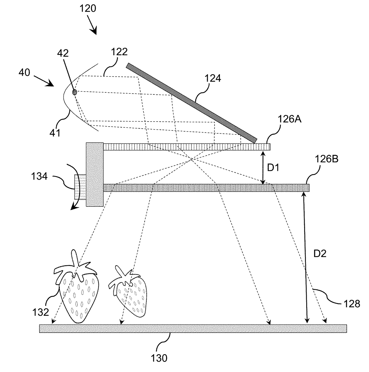
[0035]As indicated above, aspects of the invention provide an ultraviolet diffusive illuminator. The illuminator includes a reflective mirror and a set of ultraviolet radiation sources located within a proximity of the focus point of the reflective mirror. The ultraviolet radiation from the set of ultraviolet radiation sources is directed towards a reflective surface located adjacent to the illuminator. The reflective surface diffusively reflects at least 30% the ultraviolet radiation and the diffusive ultraviolet radiation is within at least 40% of Lambertian distribution. A set of optical elements can be located between the illuminator and the reflective surface in order to direct the ultraviolet radiation towards at least 50% of the reflective surface.

[0036]As used herein, unless otherwise noted, the term “set” means one or more (i.e., at least one) and the phrase “any solution” means any now known or later developed solution. It is understood that, unless otherwise specified, ea...


PUM


Abstract

A diffusive ultraviolet illuminator is provided. The illuminator can include a reflective mirror and a set of ultraviolet radiation sources located within a proximity of the focus point of the reflective mirror. The ultraviolet radiation from the set of ultraviolet radiation sources is directed towards a reflective surface located adjacent to the illuminator. The reflective surface can diffusively reflect at least 30% the ultraviolet radiation and the diffusive ultraviolet radiation can be within at least 40% of Lambertian distribution. A set of optical elements can be located between the illuminator and the reflective surface in order to direct the ultraviolet radiation towards at least 50% of the reflective surface.

Description

REFERENCE TO RELATED APPLICATIONS[0001]The current application claims the benefit of U.S. Provisional Application No. 62 / 319,752, filed on 7 Apr. 2016, U.S. Provisional Application No. 62 / 330,368, filed on 2 May 2016, and U.S. Provisional Application No. 62 / 356,696, filed on 30 Jun. 2016, all of which are hereby incorporated by reference. Aspects of the current application are related to U.S. application Ser. No. 14 / 853,075, filed on 14 Sep. 2015, U.S. application Ser. No. 15 / 472,198, filed on 28 Mar. 2017, U.S. Pat. No. 9,034,271, filed on 28 Aug. 2013, and U.S. Pat. No. 9,550,004, filed on 5 Sep. 2014, all of which are hereby incorporated by reference.TECHNICAL FIELD[0002]The disclosure relates generally to ultraviolet radiation, and more particularly, to disinfecting a surface using ultraviolet radiation.BACKGROUND ART[0003]The use of light diffusers is common in backlight illumination, which is frequently used in liquid crystal displays (LCDs). For visible light, the criterion o...

Claims


Application Information

Patent Timeline
IPC IPC(8): A61L2/10G02B5/02G02B6/02G02B3/08F21V8/00G02B5/08G02B5/10
CPCA61L2/10G02B5/0891G02B5/0284G02B6/02295G02B3/08G02B6/001G02B5/10G02B19/0095G02B6/0096G02B19/0023
Inventor DOBRINSKY, ALEXANDERSHUR, MICHAELLAKIOS, EMMANUEL
Owner SENSOR ELECTRONICS TECH
Why Eureka
Try Eureka