Device and method for monitoring a welding area and an arrangement and a method for controlling a welding operation

a technology for monitoring and welding operations, applied in auxiliary welding devices, instruments, soldering apparatus, etc., can solve the problems of uneven exposure of images created by cameras, and achieve precise welding images with a great amount of detailed information

Inactive Publication Date: 2005-02-10
GKN AEROSPACE SWEDEN AB
View PDF19 Cites 78 Cited by
  • Summary
  • Abstract
  • Description
  • Claims
  • Application Information

AI Technical Summary

Benefits of technology

[0007] One object of the invention is to provide a device for monitoring the welding area that affords opportunities for producing an image of the welding area with a greater amount of detailed information and / or precision in relation to previously known systems.

Problems solved by technology

The image created by the camera will otherwise be unevenly exposed on account of the highly luminous area around the arc and the melt.
According to previously known systems, there are problems associated with producing a precise image of the welding area with a great amount of detailed information.

Method used


Image

  • Device and method for monitoring a welding area and an arrangement and a method for controlling a welding operation
  • Device and method for monitoring a welding area and an arrangement and a method for controlling a welding operation
  • Device and method for monitoring a welding area and an arrangement and a method for controlling a welding operation

Examples


first embodiment

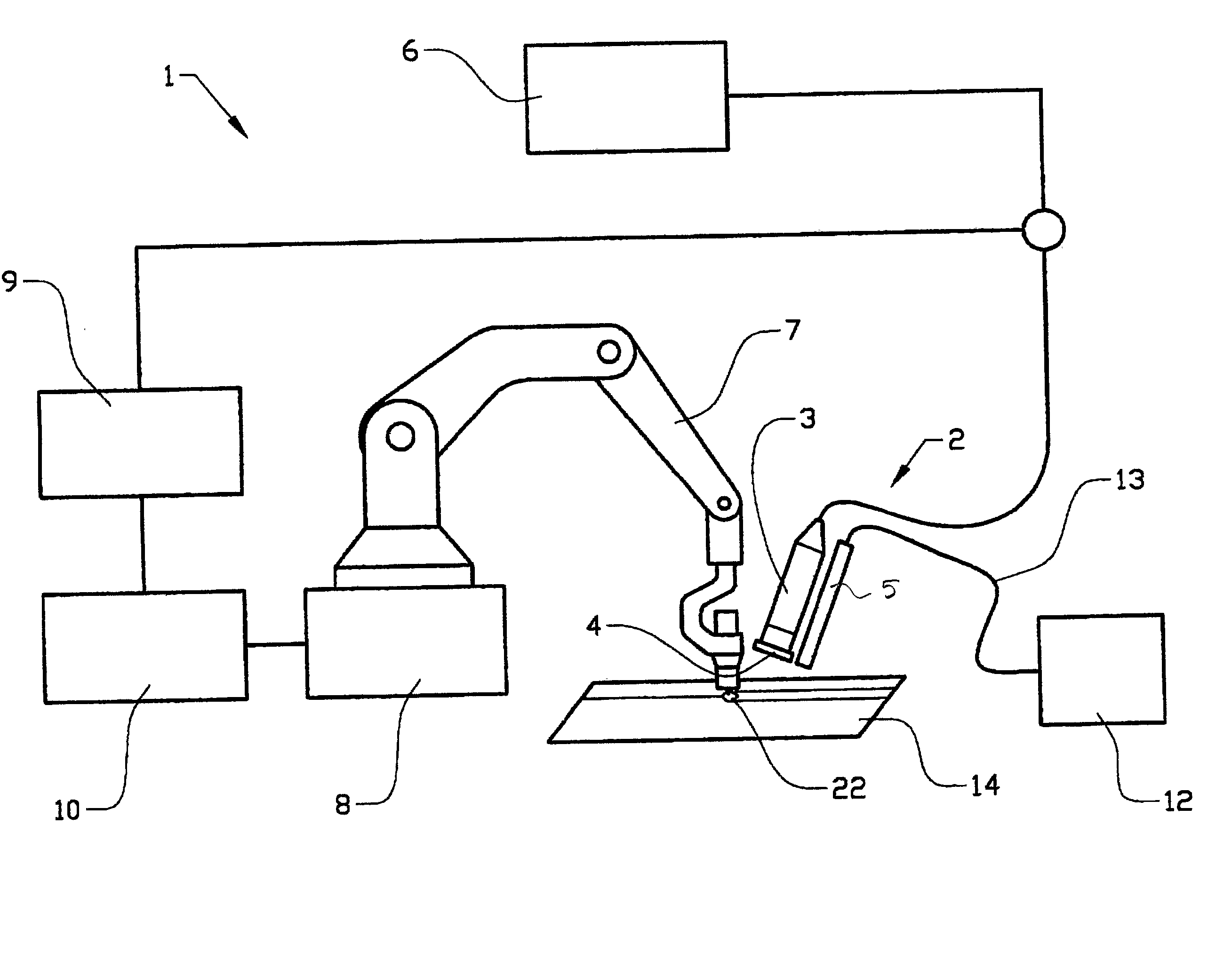
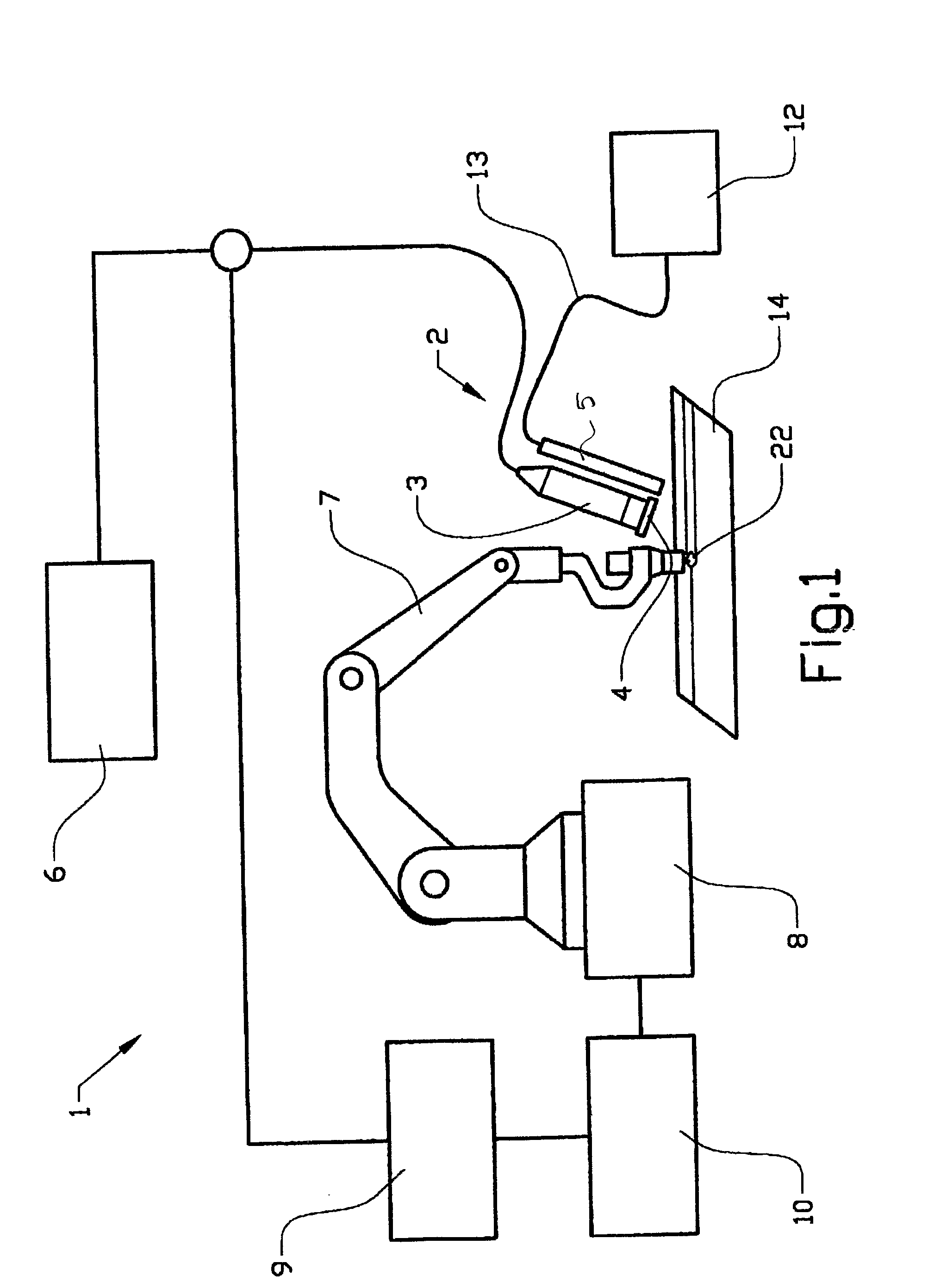
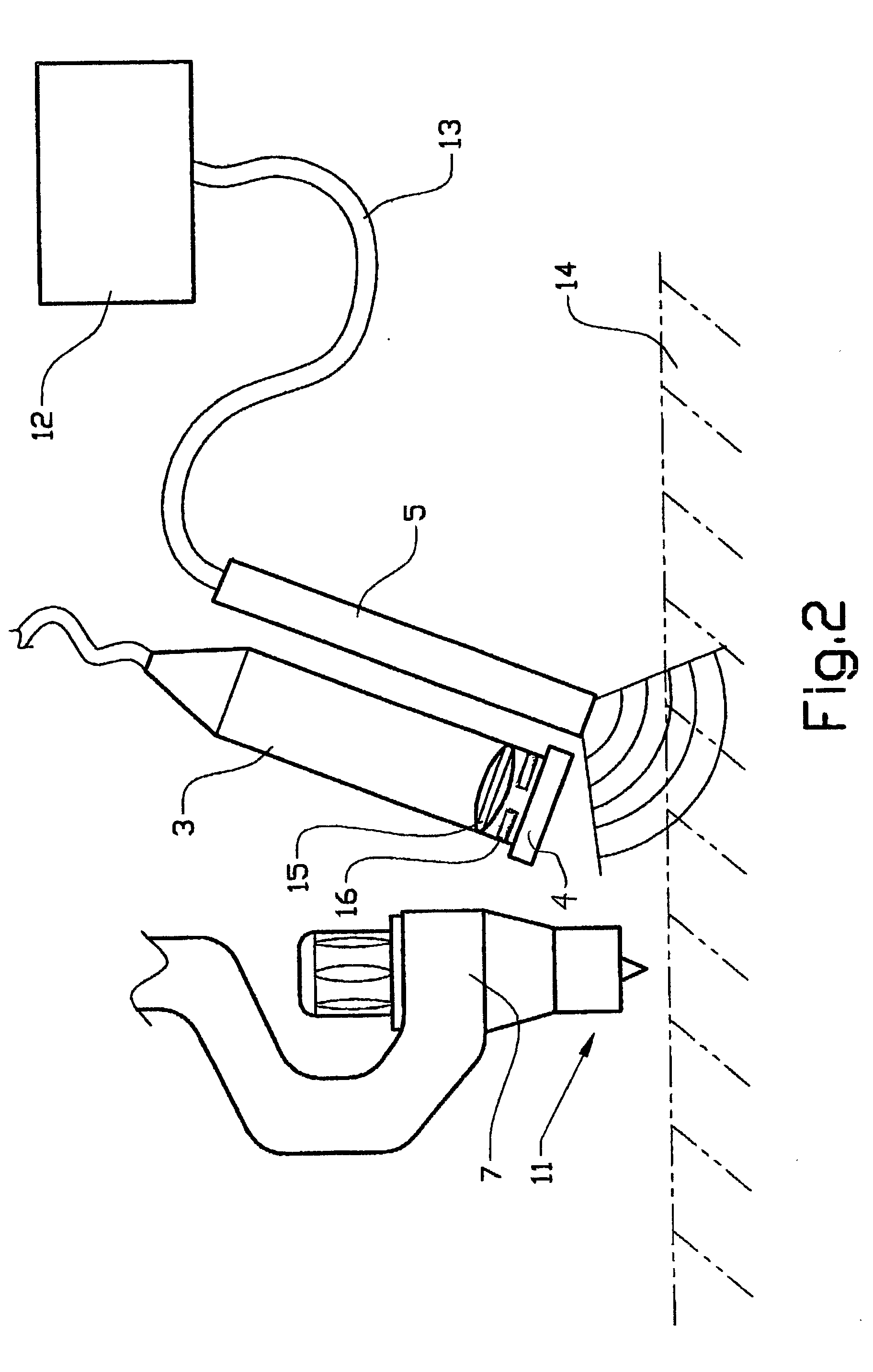
[0024]FIGS. 1 and 2 show an arrangement 1 for controlling a welding operation configured according to the teachings of the present invention. The control arrangement 1 comprises a device 2 for monitoring, or supervising, a welding area of an object 14. The device 2 comprises means 3 for reproduction of the welding area, which means 3 consists of a camera, a band-pass filter 4 arranged in front of a lens 15 of the camera, and means 5 for illumination of the welding area with ultraviolet radiation. The reproduction means 3 and the illumination means 5 are arranged on the same side of a welding means 7, in the form of a welding robot, and more specifically behind the melt 22 in the welding direction. The object 14 can consist of, for example, two plates to be welded together.

[0025] The filter 4 is adapted for separating out specific wavelengths originating from light emitted from the welding area, such as radiation and reflection from the electrode, arc and the melt. The filter 4 consi...

second embodiment

[0049] In this example, the camera 3 and the illumination means 5 are arranged so that they extend essentially vertically; that is to say, essentially at right angles to the surface and parallel to the welding head 7. The UV light is therefore emitted vertically downward from the illumination means. A first mirror 20 is arranged under the illumination means 5 and is inclined at a suitable angle, preferably the same as or close to the angle of the first mirror so as to reflect to the camera the UV illumination reflected by the welding area. In a corresponding way, a second mirror 21 is arranged under the camera 3 and is inclined at a suitable angle so as to reflect to the camera the UV illumination reflected by the welding area. This second embodiment, where the camera 3 and the illumination means are arranged next to and along the welding head 7, affords opportunities for a relatively compact device.

[0050] The UV radiation from the illumination means 5 is reflected in the melt area ...


PUM

PropertyMeasurementUnit
wavelength rangeaaaaaaaaaa
wavelengthaaaaaaaaaa

Abstract

Method and device (2) for monitoring a welding area of an object (14) in connection with welding, which device includes arrangements (3) for reproduction of the welding area, at least one filter (4) arranged in front of or in the reproduction arrangement (3), and an illumination arrangement (5) of the welding area with ultraviolet radiation. The filter (4) consists of a band-pass filter which is adapted for filtering around a wavelength within the ultraviolet wavelength range.

Description

CROSS-REFERENCE TO RELATED APPLICATIONS [0001] The present application is a continuation patent application of International Application No. PCT / SE03 / 00364 filed 4 Mar. 2003 which was published in English pursuant to Article 21(2) of the Patent Cooperation Treaty, and which claims priority to Swedish Application No. 0201057-7 filed 5 Apr. 2002. Said applications are expressly incorporated herein by reference in their entireties.FIELD OF THE INVENTION [0002] The present invention relates to a device for monitoring a welding area of an object in connection with a welding process. The device comprises (includes, but is not necessarily limited to) means for reproduction of the welding area, at least one filter arranged in front of, or in the reproduction means, and means for illumination of the welding area with ultraviolet radiation. The reproduction means can consist of, for example, a video camera, and in particular, those of the CCD (Charge Couple Device) type. An image produced is ...

Claims


Application Information

Patent Timeline
Patent Type & Authority Applications(United States)
IPC IPC(8): B23K9/095G01N21/84B23K9/127B23K26/03B23K26/08B23K26/10B23K37/00
CPCB23K9/0956B23K9/1274B23K37/00B23K26/0884B23K31/125B23K26/032
Inventor HENRIKSON, PER
Owner GKN AEROSPACE SWEDEN AB
Why Eureka
Try Eureka