
Dual zone type air conditioner for vehicle

Active Publication Date: 2017-10-12
HANON SYST
View PDF7 Cites 10 Cited by
  • Summary
  • Abstract
  • Description
  • Claims
  • Application Information

AI Technical Summary

Benefits of technology

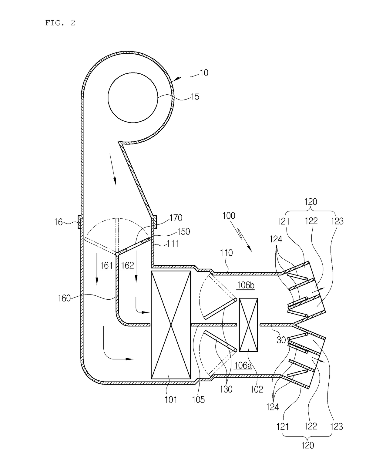
The present invention provides a dual zone type air conditioner for a vehicle that includes an air volume control door and bypass passageways. The air volume control door can control the air volume blown to the inside of the air-conditioning case by controlling the degree of opening of first and second passageways. The bypass passageways can supply a predetermined air volume to a closed passageway even if the air volume control door is at a position to close one of the air passageways. This prevents sudden changes in air volume and reduces whistle noise. The technical effects of this invention are to widen the control interval of the air volume control door and secure a predetermined cross-sectional area of the air passageway through the bypass passageways, thereby ensuring a stable air volume control and reducing errors in air volume stages.

Problems solved by technology

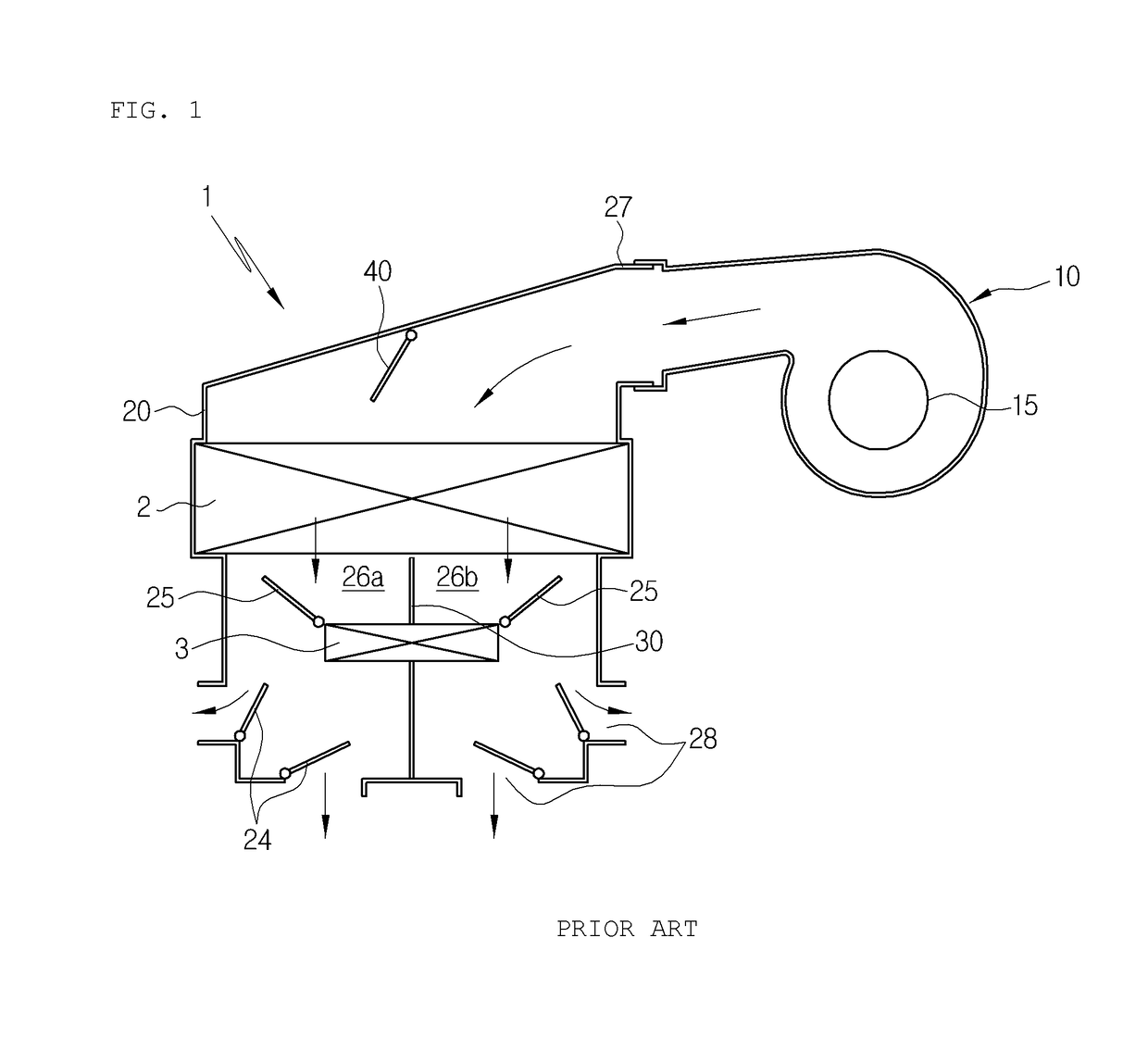
However, as shown in FIG. 1, such a conventional dual zone type air conditioner 1 has a disadvantage in that it is difficult to accurately control right and left air volumes because the cross-sectional area of the air passageways is uneven and the air volume control door 40 is mounted in front of the evaporator 2 with relatively uneven air flow.
However, the conventional dual zone type air conditioner has a disadvantage in that it generates noise, such as a whistle, because the cross-sectional area of the passageway gets gradually narrower when the air volume door moves to the position to close the left passageway or the right passageway.
Due to such a structure, when the air volume control door closes the left passageway or the right passageway, the closed passageway cannot be used even for the first-stage air volume.

Method used


Image

  • Dual zone type air conditioner for vehicle
  • Dual zone type air conditioner for vehicle
  • Dual zone type air conditioner for vehicle

Examples


Embodiment Construction

[0034]Hereinafter, reference will be now made in detail to the preferred embodiments of the present invention with reference to the attached drawings.

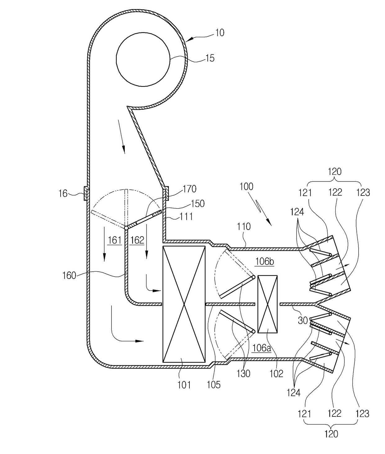
[0035]As shown in the drawing, a dual zone type air conditioner 100 for a vehicle according to a preferred embodiment of the present invention includes: an air-conditioning case 110 which has an air inflow port 111 formed at an inlet, a plurality of air outflow ports 120, such as a defrost vent 121, a face vent 122 and a floor vent 123, formed at an outlet and an air passageway formed inside the air-conditioning case to connect the air inflow port 111 with the air outflow ports 120; an evaporator 101 and a heater core 102 mounted in the air passageway to be spaced apart from each other at a predetermined interval in order; a partition wall 105 for partitioning a downstream side air passageway of the evaporator 101 into a first air passageway 106a and a second air passageway 106b; and a blower 10 mounted at the air inflow port 111 of th...


PUM


Abstract

Disclosed therein is a dual zone type air conditioner for a vehicle, which includes: an air volume control door mounted between a blower and an evaporator for controlling the degree of opening of first and second passageways so as to control the volume of air blown to the inside of an air-conditioning case; and bypass passageways disposed in the air volume control door to supply a predetermined air volume to a closed passageway even though the air volume control door is at the location to close the first passageway or the second passageway, thereby preventing a sudden change in air volume by widening a control interval of the air volume control door because the first-stage air volume can be realized even though the air volume control door closes one of the air passageways, and reducing a whistle noise by securing a predetermined cross-sectional area of the air passageway through the bypass passageways even though the cross-sectional area of the air passageway gets narrower while the air volume control door closes one of the air passageways.

Description

BACKGROUND OF THE INVENTIONField of the Invention[0001]The present invention relates to a dual zone type air conditioner for a vehicle, and more particularly, to a dual zone type air conditioner for a vehicle, which includes: an air volume control door mounted between a blower and an evaporator for controlling the degree of opening of first and second passageways so as to control the volume of air blown to the inside of an air-conditioning case; and bypass passageways disposed in the air volume control door to supply a predetermined air volume to a closed passageway even though the air volume control door is at the location to close the first passageway or the second passageway.Background Art[0002]In general, an air conditioner for a vehicle is a car part, which is installed in a vehicle for the purpose of cooling or heating the interior of the vehicle in the summer season or the winter season or removing frost from a windshield in the rainy season or the winter season to thereby se...

Claims


Application Information

Patent Timeline
IPC IPC(8): B60H1/00
CPCB60H1/00064B60H1/00678B60H2001/00092B60H2001/00192B60H2001/00135B60H1/00514B60H1/00557B60H1/00564B60H1/00664B60H1/12B60H1/22B60H2001/00164
Inventor JUNG, JAE HWANKONG, TAE YUNKIM, IN HYEOKKIM, TAE WANSEO, JEONG HUN
Owner HANON SYST
Learn More