Method Of Manufacturing A Strainer, A Strainer, And An Ejector Comprising Such A Strainer

a technology of strainer and manufacturing method, which is applied in the field of aeronautical equipment, can solve the problems of increasing the cost of the strainer, increasing the complexity of the manufacturing process, and time-consuming the design and manufacturing of the strainer, so as to reduce the cost and simplify the design and manufacturing.

Active Publication Date: 2017-10-12
SAFRAN AEROTECHNICS
View PDF3 Cites 22 Cited by
  • Summary
  • Abstract
  • Description
  • Claims
  • Application Information

AI Technical Summary

Benefits of technology

[0021]Preferably, and to simplify the design and manufacturing, and to further decrease the costs, the ma

Problems solved by technology

As a result, the design and manufacture of a strainer is time-consuming, costly and tedious.
Furthermore, it has been observed that the electrical continuity between the components of the str

Method used


Image

  • Method Of Manufacturing A Strainer, A Strainer, And An Ejector Comprising Such A Strainer
  • Method Of Manufacturing A Strainer, A Strainer, And An Ejector Comprising Such A Strainer

Examples


Embodiment Construction

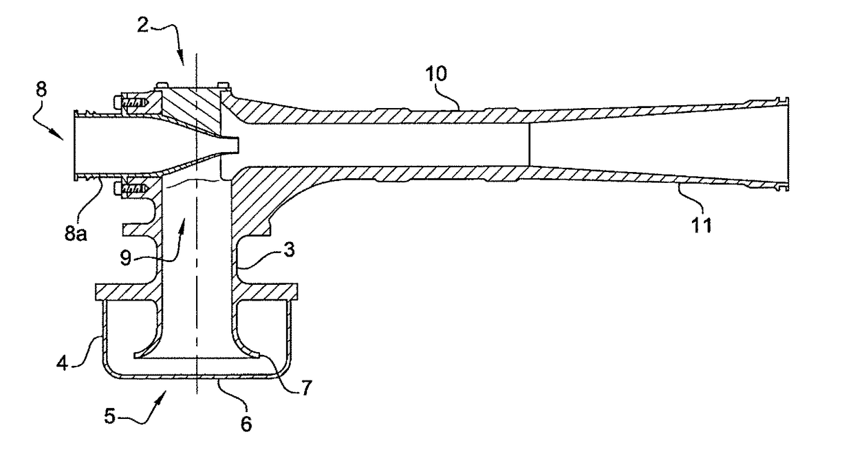
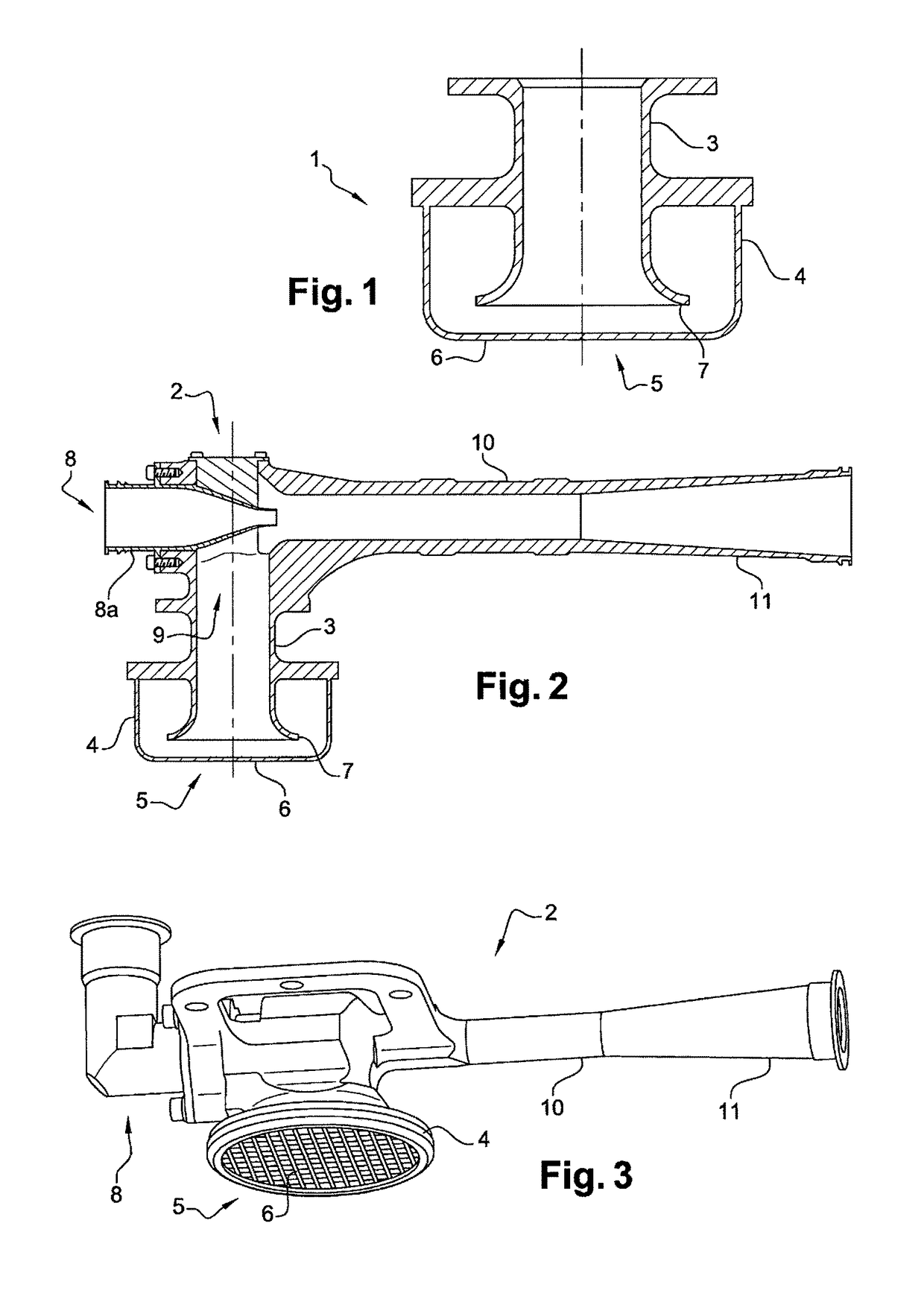
[0026]The invention broadly relates to a strainer (1), without limitation regarding its application, and will be described in relation to an ejector (2) used to transfer fuel between two fuel tanks of an aircraft or to supply fuel to an engine. The strainer (1) according to the invention is manufactured as a single part, and preferably from metal, such as aluminum. The strainer (1) can be attached to any device requiring filtration before the passage of a fluid, for example a pump or a rupture disc.

[0027]With reference to FIGS. 1 and 2, the strainer (1) comprises a conduit (3), one end of which is located with a housing (4). The housing (4) comprises a generally cylindrical shape, coaxial to the conduit (3), and has an open face (5) across from the end of the conduit (3) for the passage of the fuel. The open face (5) is closed off by a grate (6) to act as a filter. The end of the conduit (3) that is located within the housing (4) comprises a flared frustoconical shaped neck (7).

[002...


PUM

PropertyMeasurementUnit
Timeaaaaaaaaaa

Abstract

A method for manufacturing a strainer, such as a strainer of an ejector used to transfer fuel between two tanks of an aircraft or to supply fuel to an engine is provided. The strainer includes a conduit whereof a first end is intended to be connected to an inlet of the ejector, and whereof a second end is located within a housing including an open face for the passage of fuel, the open face being closed off by a grate acting as a filter. The method includes the step of manufacturing the conduit, the housing and the grate of the strainer as a single monobloc part.

Description

FIELD OF THE INVENTION[0001]The present invention relates to the technical field of aeronautics, and more particularly relates to a method for manufacturing a strainer, such as a strainer of an ejector used to transfer fuel between two fuel tanks of an aircraft or to supply an engine with fuel.[0002]The invention also relates to an improved strainer, and an ejector comprising such a strainer. The strainer according to the invention may be attached to any type of device that requires filtration before the passage of a fluid, for example a pump, or a rupture disc calibrated to burst at a predetermined pressure, implemented within an installation that is subjected to pressure.BACKGROUND OF THE INVENTION[0003]In the aeronautics field, it is known to use ejectors supplied by a motive flow, for example supplied by a reactor outlet or by a pump to transfer fuel between two fuel tanks of an aircraft.[0004]Indeed, when the tank unit of the aircraft is made up of several tanks, it is necessar...

Claims


Application Information

Patent Timeline
IPC IPC(8): B64D37/00B01D35/30B64D37/04B33Y70/00B33Y80/00B01D29/03B33Y10/00B22F10/00
CPCB64D37/005B01D29/03B01D35/30B64D37/04B33Y70/00B33Y80/00B33Y10/00B22F3/00F02M37/22F02M61/165F02M61/168B32B15/00F02M37/0011F02M37/0082F02M37/025F02M37/50
Inventor CORMAN, FRANCOIS
Owner SAFRAN AEROTECHNICS
Why Eureka
Try Eureka