Planar lighting device

a lighting device and planar technology, applied in the field of planar lighting devices, can solve problems such as inacceptable brightness variations

Inactive Publication Date: 2017-10-12
MINEBEAMITSUMI INC
View PDF22 Cites 1 Cited by
  • Summary
  • Abstract
  • Description
  • Claims
  • Application Information

AI Technical Summary

Benefits of technology

[0005]It is an object of the present invention to at least

Problems solved by technology

Such a corrugated optical sheet may cause an unacceptable brightness variation on a scr

Method used


Image

  • Planar lighting device
  • Planar lighting device
  • Planar lighting device

Examples


embodiment

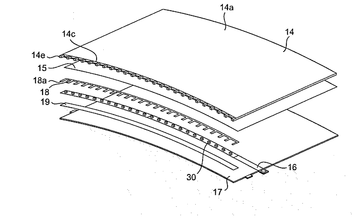
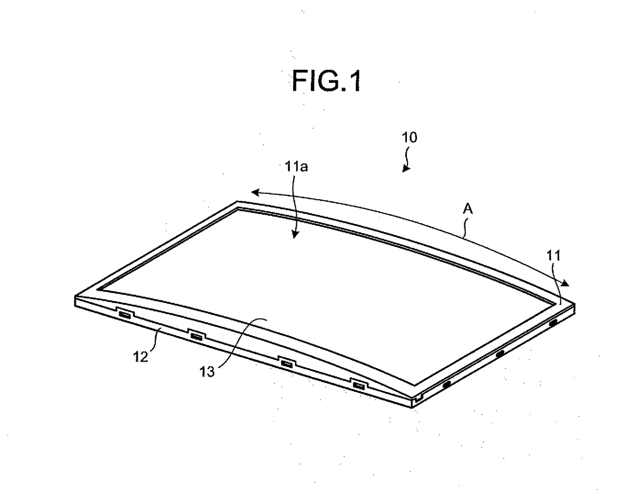
[0025]FIG. 1 is a perspective view illustrating an example of an external appearance of the planar lighting device according to the embodiment. As illustrated in FIG. 1, this planar lighting device 10 according to the embodiment includes an upper frame 11, a lower frame 12, and an optical sheet 13. The upper frame 11 is located at the upper side and the lower frame 12 is located at the lower side of the planar lighting device 10 when the planar lighting device 10 is laid flat.

[0026]The upper frame 11 has an aperture 11a. The upper frame 11 has a curved shape. The upper frame 11 is an example of a first frame. Light emitted from the optical sheet 13 passes through the aperture 11a to illuminate a liquid crystal display device, which is not illustrated. In other words, the planar lighting device 10 is used as a backlight of the liquid crystal display device. The optical sheet 13 is a laminate of a plurality of types of optical sheets. In the present embodiment, the optical sheet 13 is...


PUM


Abstract

A planar lighting device according to an embodiment includes: a light guide that has flexibility and receives light from a side surface and emits the light from a light-emitting surface; a light source disposed close to the side surface and emits light that enters the side surface; a first frame having a curved shape and having an aperture; a second frame having a curved surface for sandwiching the light guide between the first frame and the curved surface such that the light-emitting surface faces the aperture; and an optical sheet disposed close to the light-emitting surface with at least a part of an edge portion of the optical sheet being disposed in a space defined by the first frame and the light guide, the part being separated from the first frame.

Description

CROSS-REFERENCE TO RELATED APPLICATION(S)[0001]The present application claims priority to and incorporates by reference the entire contents of Japanese Patent Application No. 2016-078323 filed in Japan on Apr. 8, 2016.BACKGROUND OF THE INVENTION1. Field of the Invention[0002]The present invention relates to a planar lighting device.2. Description of the Related Art[0003]Planar lighting devices used in a curved state are known. Such planar lighting devices include, for example, a flexible light guide, a flexible lens sheet, and a frame that houses the light guide and the lens sheet in a curved state. Conventional technologies are described in Japanese Laid-open Patent Publication No. 2010-140831 and Japanese Laid-open Patent Publication No. 2014-122973, for example.[0004]When such a planar lighting device is installed in, for example, a vehicle, the planar lighting device will be used in a wide range of temperature conditions from −40° C. to +95° C. When the temperature of a working ...

Claims


Application Information

Patent Timeline
IPC IPC(8): F21V8/00
CPCG02B6/0081G02B6/0073G02B6/0055G02B6/0088G02F1/133615G02B6/0085G02F2203/60G02F2201/54
Inventor TAKADA, SHOHEITOKUNAGA, HIDEYUKI
Owner MINEBEAMITSUMI INC
Why Eureka
Try Eureka