Perforating cap for a flexible tube

a flexible tube and perforating cap technology, applied in the field of flexible tubes, can solve the problems of the closure liner being mixed with the contents of the tube, and achieve the effects of reducing the number of cap turns, saving time for cutting the closure liner, and facilitating the handling of the assembly by the user

Active Publication Date: 2017-10-19
ALBEA SERVICES SAS
View PDF5 Cites 20 Cited by
  • Summary
  • Abstract
  • Description
  • Claims
  • Application Information

AI Technical Summary

Benefits of technology

[0009]Thus, the invention is based on the applicant observing that a cut can be made in a closure liner with a reduced number of cap turns by distinguishing between the angular range required to perforate the closure liner, which will substantially depend on the elasticity thereof, and the angular range needed for the cut. By then providing an angular cutting range below 360°, a fast and clean partial cut of the closure liner is obtained during the first use of the tube. This facilitates the handling of the assembly by the user, particularly by saving time for cutting the closure liner.

Problems solved by technology

Indeed, with a full cut, the closure liner risks being mixed with the contents of the tube.

Method used


Image

  • Perforating cap for a flexible tube
  • Perforating cap for a flexible tube
  • Perforating cap for a flexible tube

Examples


Embodiment Construction

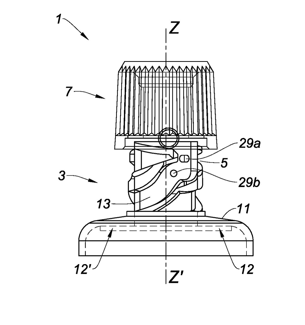
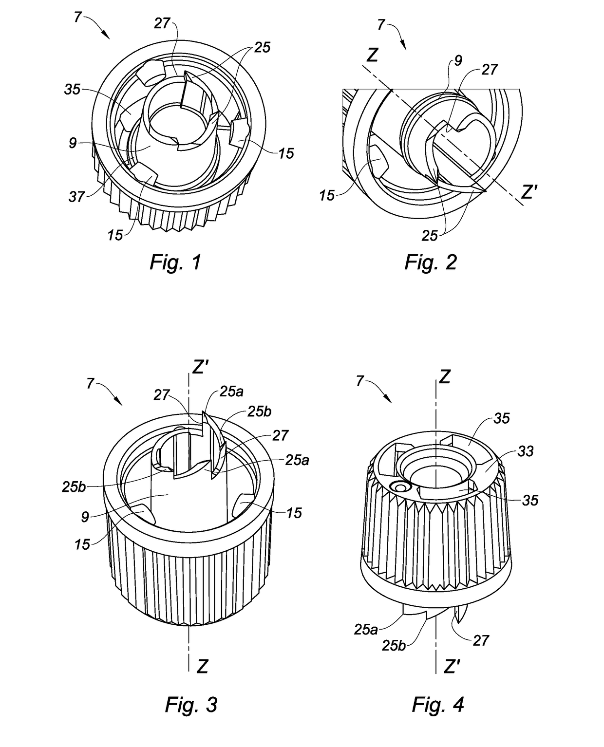
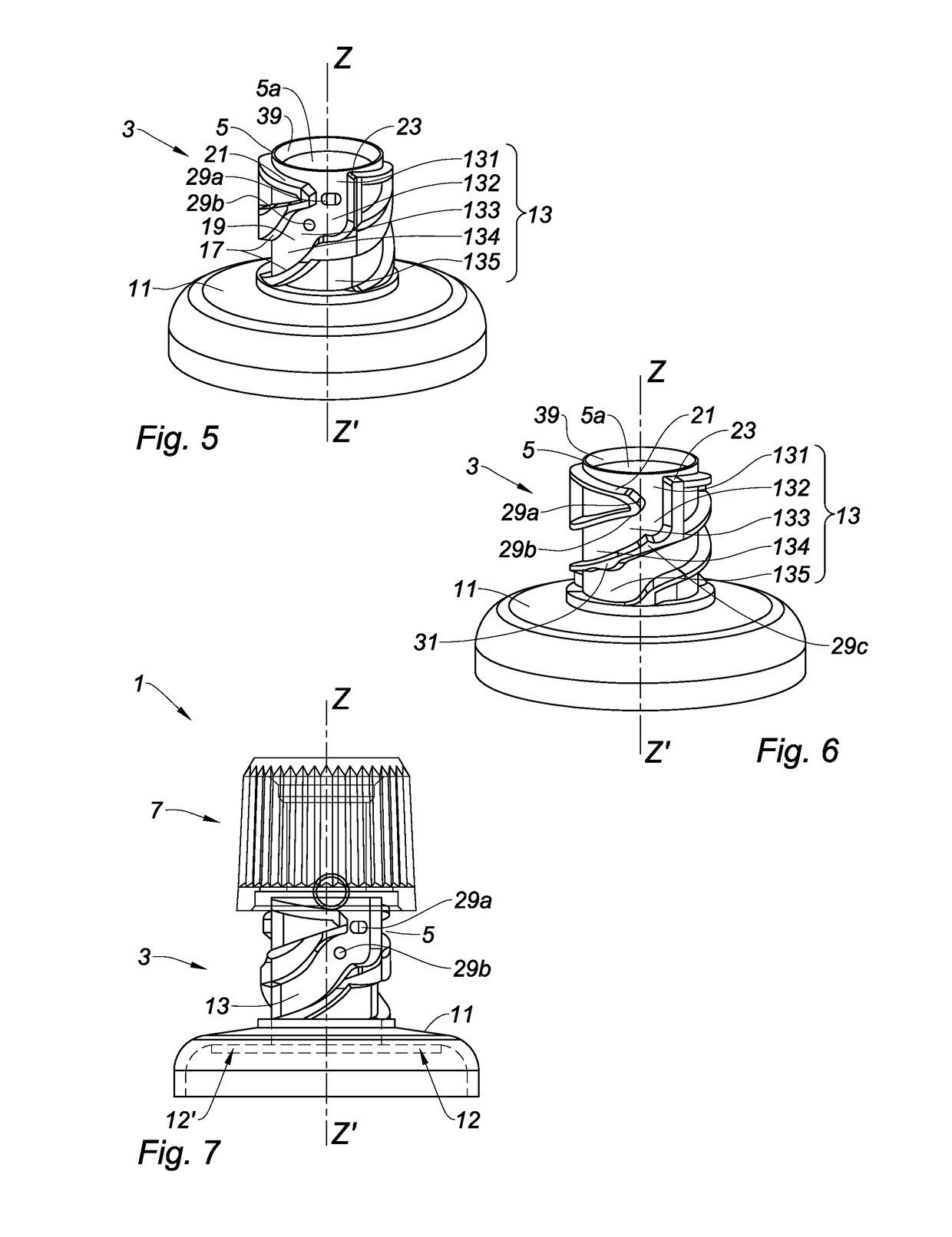
[0060]A tube closure assembly is described. The assembly 1 includes a tube head 3 including a neck 5 and a closure liner sealing the neck 5 and a cap 7 including a punch 9 configured to cut the closure liner. The tube head 3, a first variant of which is shown in FIGS. 5 and 7 to 10, a second variant of which is shown in FIG. 6 and a third variant of which is shown in FIGS. 11 and 12, includes the neck 5 defining a longitudinal axis Z-Z′, a shoulder 11 and a full insert 12 forming the closure liner 12′ at its centre. The closure liner seals the neck 5 in the lower part thereof. As shown herein, the neck 5 and the shoulder 11 are designed as a single-piece and are integrally formed.

[0061]The neck 5 in this case is in the form of a cylinder extending from an upper end, which is located towards the outside of the tube, towards a lower end, which is opposite the upper end and is directed towards the inside of the tube. The upper end has a discharge hole 5a allowing the product that is co...


PUM


Abstract

The present invention relates to a tube closure assembly. The assembly includes a tube head that includes a neck and a closure liner sealing said neck, and a cap that includes a punch provided with at least one tooth. The one or more teeth are configured to peripherally cut said closure liner. The cap is configured to transition from an open flush position, in which the one or more teeth are flush with said closure liner, to a perforation position, in which the one or more teeth perforate the closure liner, then from the perforation position to an end-of-travel position allowing partial cutting of the closure liner, the transition from the perforation position to the end-of-travel position being carried out with an angular rotational range below 360°.

Description

CROSS REFERENCE TO RELATED APPLICATIONS[0001]This application claims priority under 35 U.S.C. §119(a) to French Patent Application Serial Number 1653453, filed Apr. 19, 2016, French Patent Application Serial Number 1655899, filed Jun. 23, 2016, and French Patent Application Serial Number 1751859, filed Mar. 7, 2017, the entire teachings of which are incorporated herein by reference.BACKGROUND OF THE INVENTIONField of the Invention[0002]The present invention relates to the field of flexible tubes including a closure liner sealing the neck prior to the first use of the tube, and to a perforating cap adapted to perforate the closure liner.Description of the Related Art[0003]Tubes are known that are provided with a closure liner associated with a perforating cap including a punch adapted to perforate the closure liner.[0004]The closure liner allows the product contained inside the tube to be hermetically preserved while it is stored, prior to its first use, which represents a significan...

Claims


Application Information

Patent Timeline
Patent Type & Authority Applications(United States)
IPC IPC(8): B65D51/22B65D1/02B65D41/02
CPCB65D51/225B65D1/0246B65D41/02B65D2251/0093B65D2251/0028B65D2251/009B65D2251/0015B65D51/22B65D51/222B65D41/08B65D35/44B65D51/243B65D41/04B65D41/06B65D47/36
Inventor DEFERT, SYLVAIN
Owner ALBEA SERVICES SAS
Why Eureka
Try Eureka