Deploying mineral insulated cable down-hole

a technology of mineral insulated cable and downhole, which is applied in the direction of fluid removal, borehole/well accessories, ohmic-resistance heating, etc., can solve the problems of further contributing to expense, method is expensive, and expensive operation, and achieves quick and efficient operation, low cost and efficiency, and equipment use.

Active Publication Date: 2017-10-19
CONOCOPHILLIPS CO
View PDF10 Cites 8 Cited by
  • Summary
  • Abstract
  • Description
  • Claims
  • Application Information

AI Technical Summary

Benefits of technology

[0041]This invention allows deployment of MI heater cable into a well in a low cost and efficient manner. The equipment used is minimal and requires a limited number of workers to operate. Likewise, removing the MI heater cable from the well is a quick and efficient operation.
[0042]This method avoids having to remove the entire production tubing with the pump attached in the event the MI cable heater fails or there is a desire to replace it with a MI cable heater with different characteristics.
[0043]This method avoids the expense of the coiled tubing encapsulation previously described and also avoids the time and expense of utilizing a service coiled tubing unit to deploy and remove the MI heater cable. However, if CT coil is already in place, it can be used as dedicated tubing inside which the MI cable heater is deployed.

Problems solved by technology

While at least partially effective, this method is costly because the coiled tubing has to be procured and the MI cable inserted into the coiled tubing, which is an expensive operation.
Generally, this procedure is done far from the field location and the cost of shipping the MI cable with the coiled tubing inside further contributes to expense due to the size and weight of the assembly.
Furthermore, the equipment required to install the MI cable encapsulated in the coiled tubing is expensive to operate on a daily basis, requiring additional personnel.

Method used


Image

  • Deploying mineral insulated cable down-hole
  • Deploying mineral insulated cable down-hole
  • Deploying mineral insulated cable down-hole

Examples


Embodiment Construction

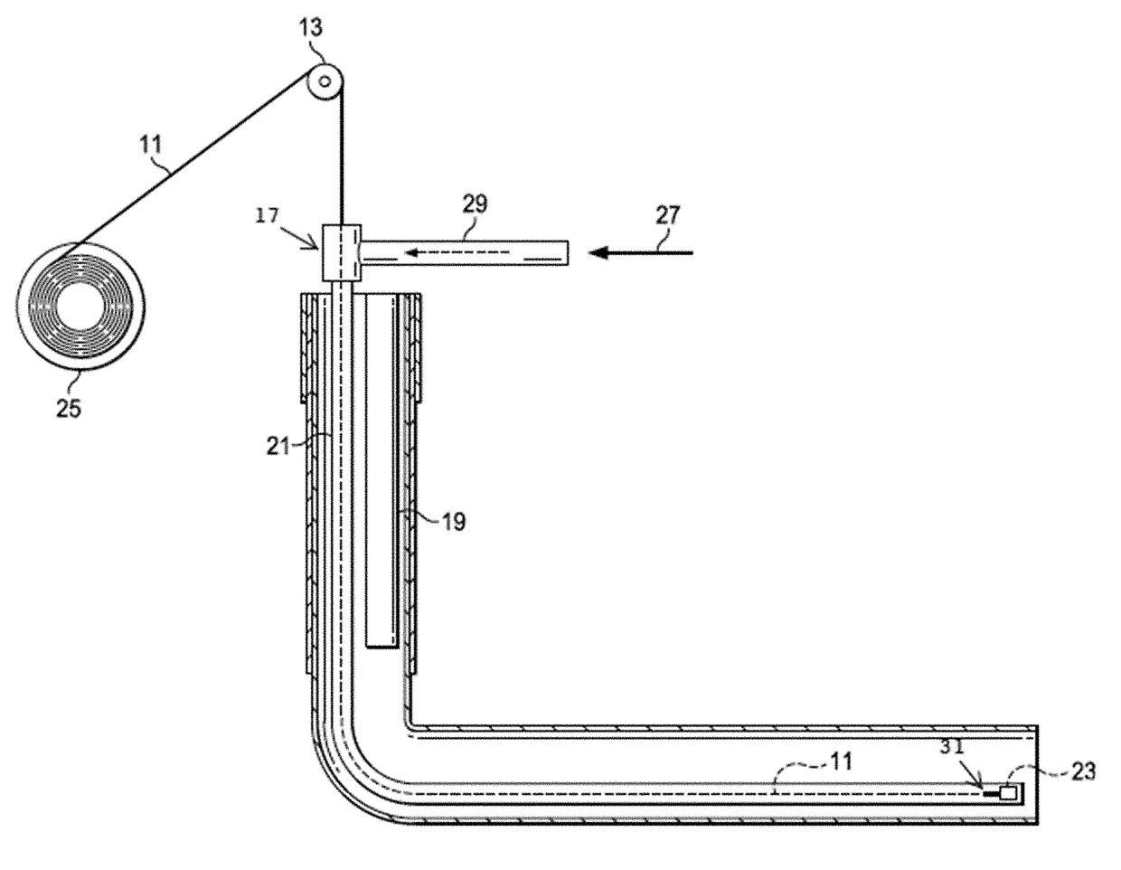
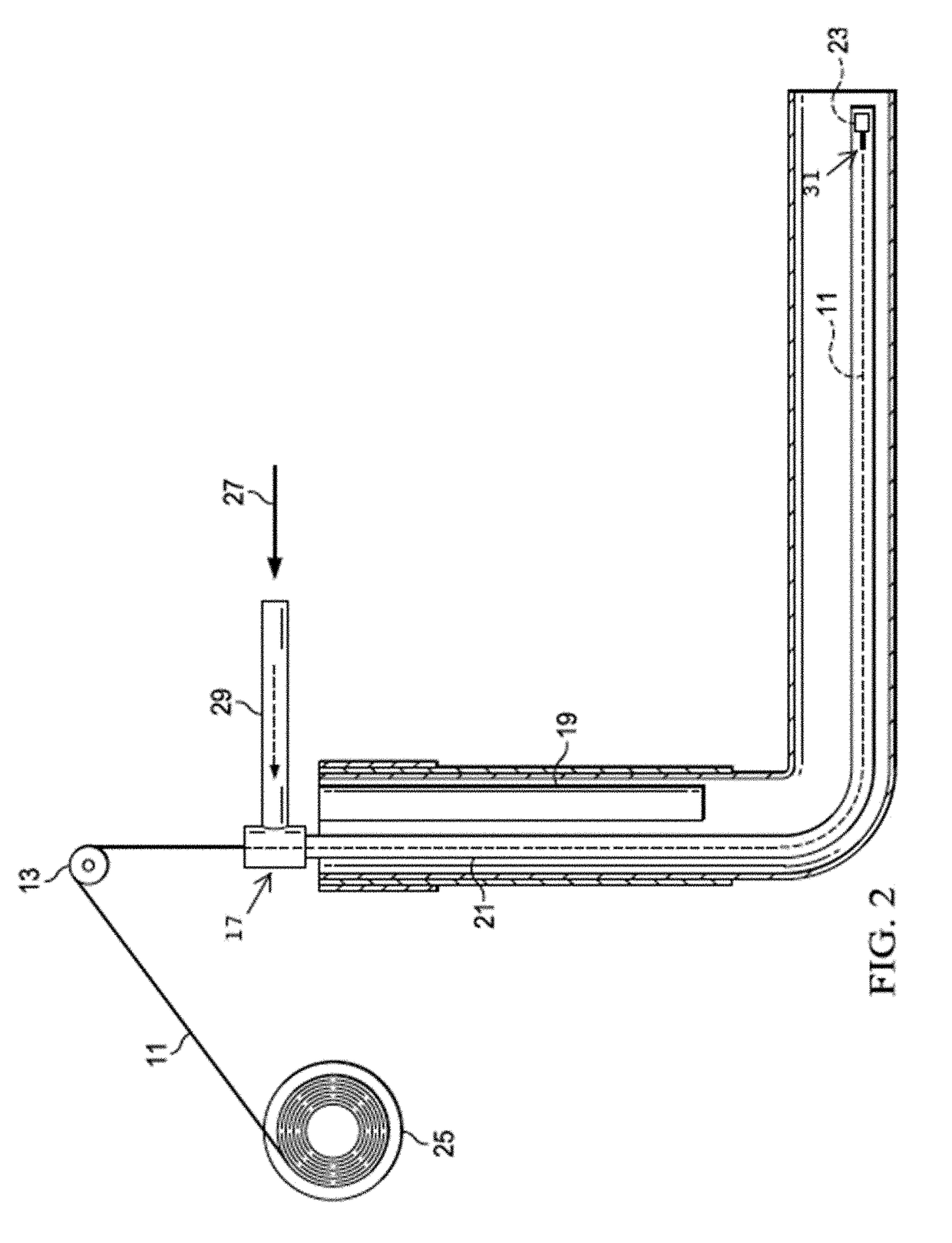
[0079]The disclosure provides a novel method of deploying an MI Cable heater down-hole that avoids the complex and expensive method using CT encapsulation, or difficult deployments to the outside of e.g., a stinger tube.

[0080]SPE-167347 (2013) by Parman, for example, teaches a heater that consists of a multi-stage, 3 cable MI heater in the pay zone, powered via ESP cable (see petrowiki.org / ESP_power_cable). The MI heater was constructed to provide highest power output (and heat) near the toe, somewhat less power in the middle section of the lateral, and less still near the heel. A “cold lead” section was also included to ensure that the ESP cable and connection components do not overheat. This three-cable system was deployed down-hole, attached to the outside of a stinger pipe in the horizontal section of pipe. Deployment details are not provided, but clearly deploying three cables down a significant length of horizontal pipe is not trivial. The invention herein described teaches ho...


PUM


Abstract

Methods, system and devices for deploying an MI cable heater down-hole into a hydrocarbon reservoir are provided, wherein one or more MI cables are housed inside a protective jacket, and connected to a pump-in device. The pump-in device allows the cable to be deployed by pumping fluid down-hole, and the pump-in device catches the fluid and pulls the cable down-hole, even in a horizontal well.

Description

PRIOR RELATED APPLICATIONS[0001]This application is a non-provisional application which claims benefit under 35 USC §119(e) to U.S. Provisional Application Ser. No. 62 / 322,607 filed Apr. 14, 2016, entitled “DEPLOYING MINERAL INSULATED CABLE DOWN-HOLE,” which is incorporated herein in its entirety.FEDERALLY SPONSORED RESEARCH STATEMENT[0002]Not applicable.FIELD OF THE DISCLOSURE[0003]The disclosure generally relates to methods of deploying mineral insulated heater cable into hydrocarbon wells.BACKGROUND OF THE DISCLOSURE[0004]The Arctic is estimated to hold the world's largest remaining untapped gas reserves and some of its largest undeveloped oil reserves. These reserves, if tapped, may provide a local energy source for North America. However, the Arctic presents harsh physical conditions that make the production of oil in this environment particularly challenging, including extreme remoteness, ice, extreme low temperatures, and in winter long periods of darkness.[0005]Other cold re...

Claims


Application Information

Patent Timeline
Patent Type & Authority Applications(United States)
IPC IPC(8): E21B43/24E21B23/14E21B23/10H05B3/56
CPCE21B43/2401E21B23/10H05B2214/03H05B3/56H05B2203/021E21B23/14E21B23/08E21B33/072
Inventor MILLS, JIM A.ECK, DAN
Owner CONOCOPHILLIPS CO
Why Eureka
Try Eureka