
Lift device and pneumatic actuator therefor

a technology of pneumatic actuator and lifting device, which is applied in the direction of lifting device, tyre repairing, tyre parts, etc., can solve the problems of no specific tools for the installation of tires in the automotive industry, the tire size and weight of the tires used on cars and light trucks is increasing, and the mechanics are installing problems, etc., to achieve quick and efficient lifting operation and low manufacturing cost

Inactive Publication Date: 2006-10-19
VESA AARNO
View PDF12 Cites 25 Cited by
  • Summary
  • Abstract
  • Description
  • Claims
  • Application Information

AI Technical Summary

Benefits of technology

[0017] The wheel lift device as described herein uses a pneumatic, air operated cylinder to lift the carriage assembly very quickly to the desired height required by the operator. Automotive workshops are commonly provided with compressors and storage tanks for supplying air or other gas under pressure to power various pneumatic tools. Accordingly, a wheel lift device which relies upon a pneumatic lift mechanism is of low cost to manufacture as no additional motors and the like are required to generate sufficient to force to lift a large range of automotive tires in a very quick and efficient lifting operation. Location of the lift controls directly on the support frame ensures quick access for lifting and lowering tires in proximity to the task being performed.

Problems solved by technology

In the automotive industry, the tires used on cars and light trucks are getting larger and heavier, creating a problem for the technicians installing them.
As of now there are no specific tools for the installation of tires for the automotive industry.
Most of these tools are unsuitable for use in the automotive industry due to their design.
These tools are of heavy construction and have limited height capabilities to a (maximum of 14 inches), making them awkward to use.
One of the other drawbacks to current heavy tire lift design is the means which the tire is lifted: either hydraulically pumped cylinder or by cable crank means.
Each of these methods is very slow and time consuming and generally not considered worthwhile for smaller automotive tires.
None of the tools described in the noted prior art patents are suitably arranged for quickly lifting and lowering vehicle wheels thereon with a simple and low cost device.
Either a complex jack or hydraulic actuator is required for lifting the wheels thereon in a slow and time consuming operation.
Such a motor is particularly slow and provides a limited number of lifting cycles before charging is required.
Recharging time thus limits continuous use of the lifting device.
The lifting device by Rotary™ is limited in its use according to several aspects.
The most prohibitive is the tall mast which will hit the fenders of most vehicles when the tool is pushed into the wheel well to install a tire.
The second are the small wheels and casters the tool sits on, which make the tool hard to use in a shop environment.
Thirdly, the device is limited to a 110 lbs capacity due to the electric motors used.
Commonly available 19.5 inch diameter wheels rims with tires often weigh 130 lbs and accordingly the lifting device available by Rotary™ could not raise many wheels used on one and two ton vehicles.

Method used


Image

  • Lift device and pneumatic actuator therefor
  • Lift device and pneumatic actuator therefor
  • Lift device and pneumatic actuator therefor

Examples


Embodiment Construction

[0048] The present invention relates to a pneumatic lifting device that is suitable for lifting tires and / or brake drums from the ground to approximately chest height quickly and safely. The invention also relates to a pneumatic actuator device which is particularly suited for use with the lifting device described herein.

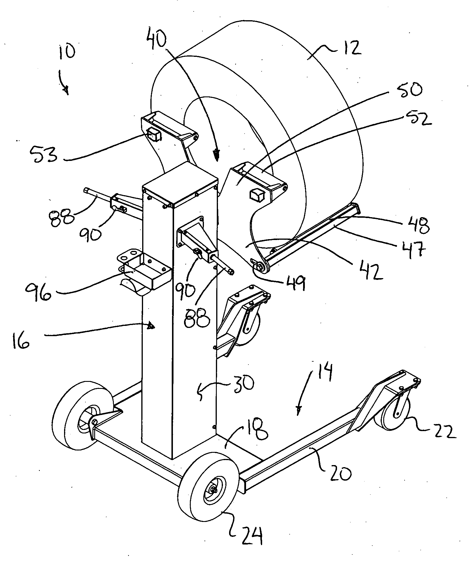
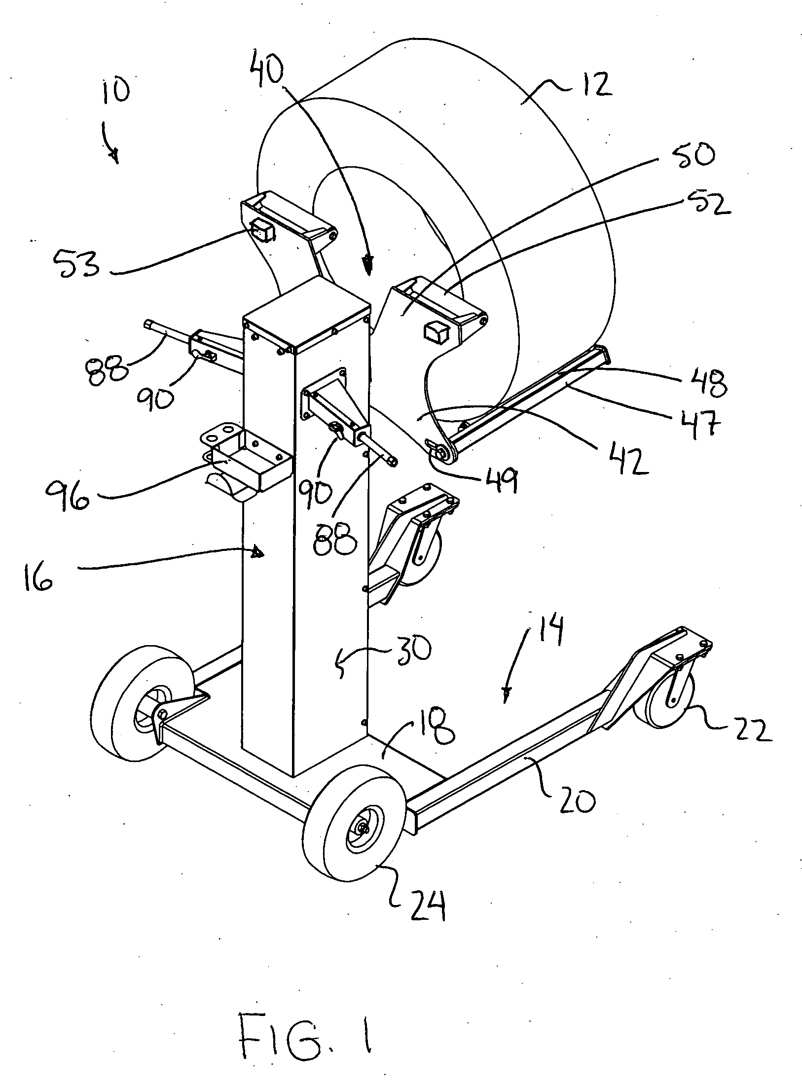
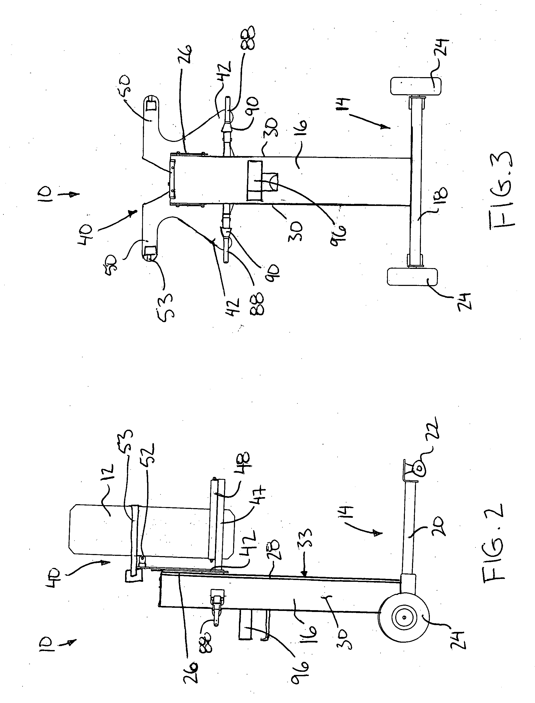
[0049] Referring to the accompanying drawings there is illustrated a wheel lifting device generally indicated by reference numeral 10. The device 10 is particularly suited for lifting car and truck tires individually thereon from the ground to a wheel hub when the vehicle is supported spaced above the ground on a vehicle lift. The wheel 12 can be rotated about its axis when supported on the device 10, and can be moved about by rolling the device 10 along the ground. Lifting force for the wheel is provided by conventional compressed air systems typically available in automotive garages and the like. The device is arranged for coupling to a supply line from a typical...


PUM


Abstract

A wheel lift device includes an upright extending upwardly from a wheeled base. A carriage slides along the upright and includes a wheel support to support an automotive wheel thereon. A pneumatic lift mechanism is housed in the upright and is coupled to the carriage. A lift control comprises a supply valve to couple the lift mechanism to a source of compressed gas for lifting and a vent valve to couple the lift mechanism to a vent for lowering. The lift device has rapid response, is of low cost and requires minimal maintenance when arranged to connect to conventional compressed air supply lines of the type readily available in automotive servicing stations. Location of the lift controls directly on the upright ensures quick access for controlling the lifting and lowering of wheels in direct proximity to the task being performed.

Description

[0001] This application hereby claims the benefit under 35 U.S.C. Section 119(e) of U.S. provisional application 60 / 664,951 filed Mar. 25, 2005.FIELD OF THE INVENTION [0002] The present invention relates to a pneumatic lifting device that is particularly suitable for lifting tires and / or brake drums, and also relates to a linear pneumatic actuator which is particularly suited for use with the lifting device described herein. BACKGROUND [0003] In the automotive industry, the tires used on cars and light trucks are getting larger and heavier, creating a problem for the technicians installing them. Employers and employees are concerned about back injuries and other muscle strains. As of now there are no specific tools for the installation of tires for the automotive industry. Many different styles of tire lifts have been designed, sold and patented for the heavy truck industry. Most of these tools are unsuitable for use in the automotive industry due to their design. These tools are de...

Claims


Application Information

Patent Timeline
Patent Type & Authority Applications(United States)
IPC IPC(8): B66F9/20
CPCB66F9/18B60B29/002
Inventor VESA, AARNO
Owner VESA AARNO
Learn More