Electricity storage module

Inactive Publication Date: 2017-10-26
AUTONETWORKS TECH LTD +2
View PDF2 Cites 5 Cited by
  • Summary
  • Abstract
  • Description
  • Claims
  • Application Information

AI Technical Summary

Benefits of technology

[0017]According to the present design, it is possible to provide an electricity storage module in

Problems solved by technology

In the electricity storage module having such a configuration, if the number of power storage elements that constitute the electricity storage module increases, the number of detection terminals connected to the power storage elements also increases, and this has been problematic in that the operation for connecting the lead terminals and the detection terminals is time-consuming.
With such a configuration, a problem of corrosi

Method used


Image

  • Electricity storage module
  • Electricity storage module
  • Electricity storage module

Examples


Example

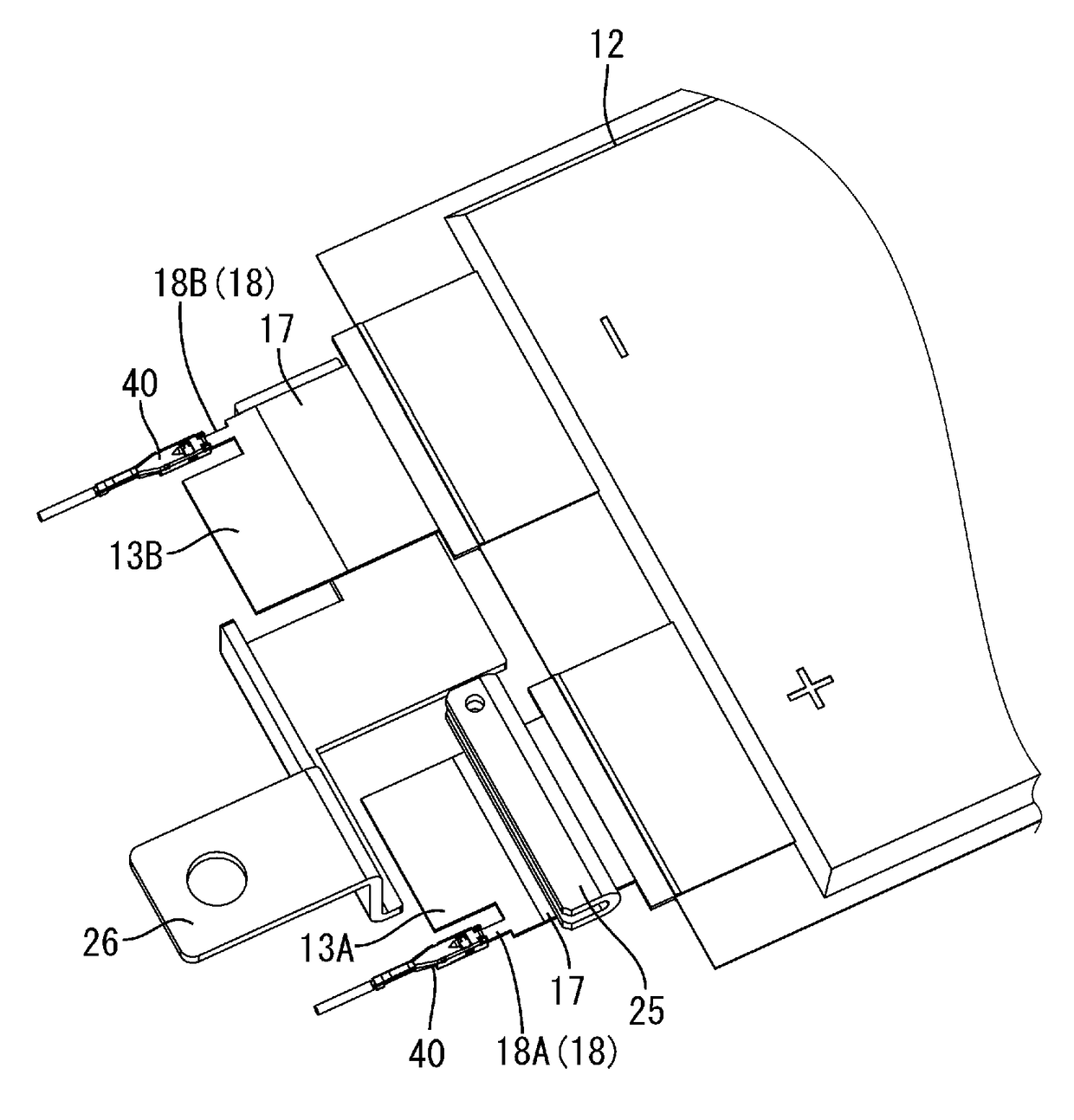
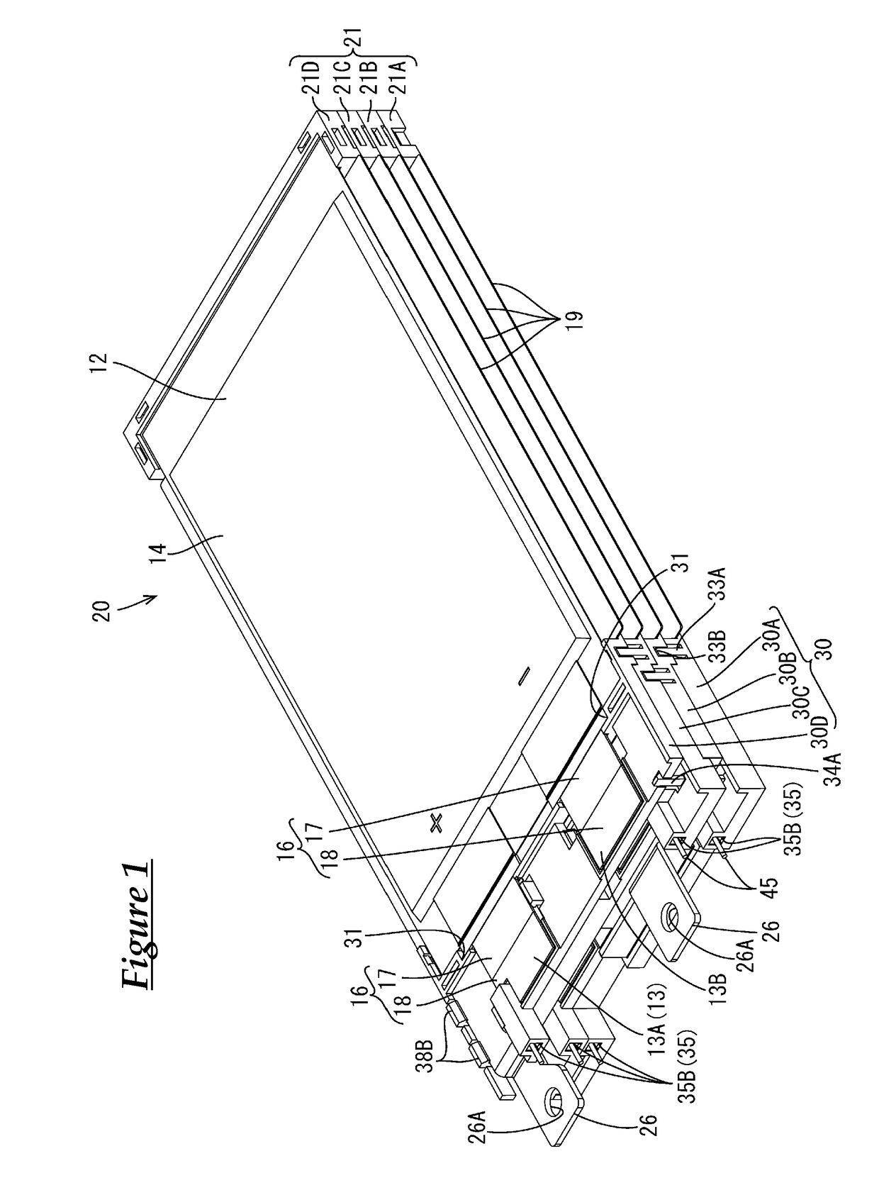
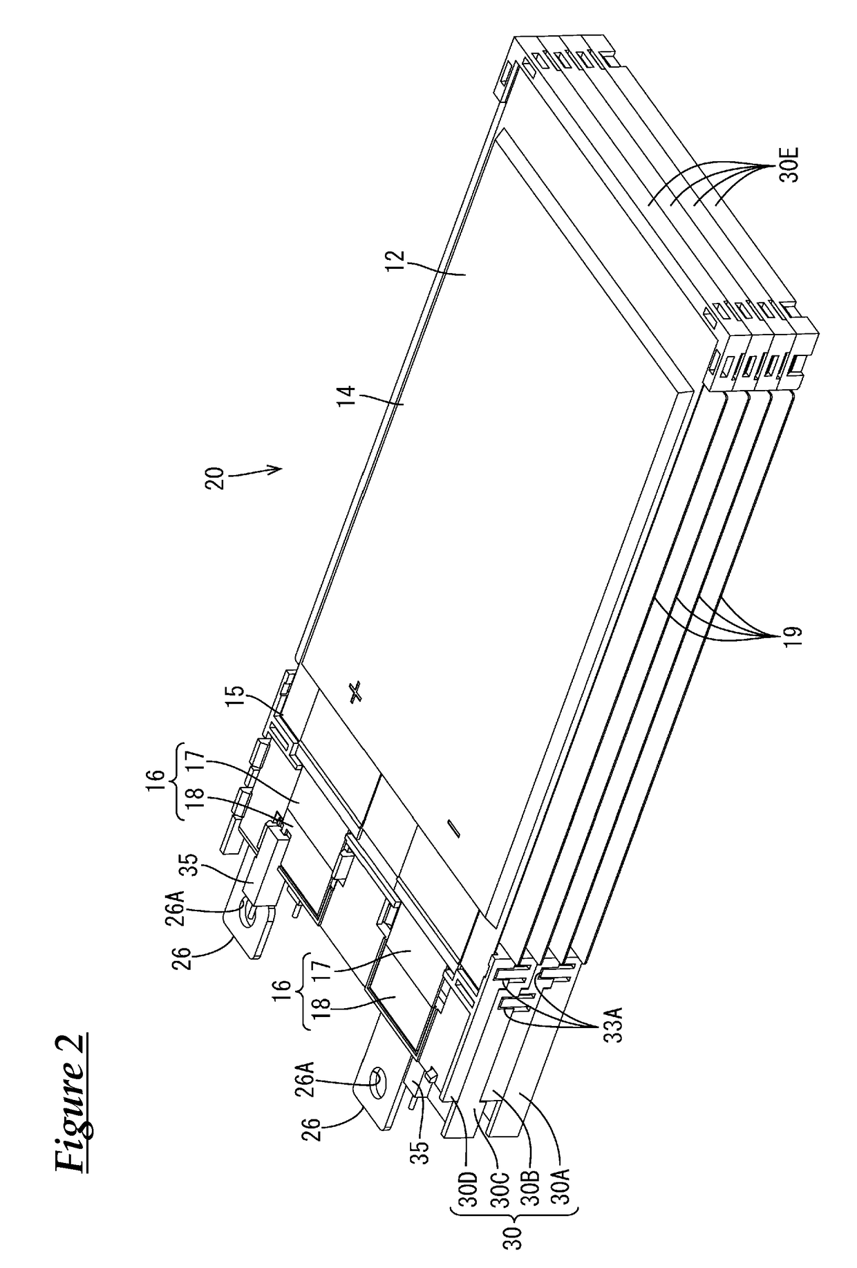
[0045]Embodiment 1 will be described with reference to FIGS. 1 to 27. In the drawings, reference signs may be given to one of a plurality of the same members, and reference signs may be omitted from the other same members. In the following description, the terms “front” and “back” respectively refer to the left side and right side of FIG. 4.

[0046]An electricity storage module of the present embodiment includes a power storage element group 11 obtained by stacking a plurality of power storage elements 12 (four in the present embodiment) having lead terminals 13 protruding from their side edges. In the present embodiment, as shown in FIG. 1, the power storage elements 12 that constitute the power storage element group 11 are stacked in a state in which the power storage elements 12 are placed on heat transfer members 19 to which holding members 30 are attached. A power storage unit 21 is obtained by placing a power storage element 12 on a heat transfer member 19 to which a holding mem...


PUM


Abstract

An electricity storage module includes a power storage element group obtained by stacking a plurality of power storage elements each having a lead terminal that protrudes from a side edge. The lead terminals are each provided with a terminal connection portion for electrically connecting the lead terminals that are adjacent in a direction in which the power storage elements are stacked, and a detection terminal portion that is electrically connectable to a device for detecting and controlling states of the respective power storage element.

Description

CROSS REFERENCE TO RELATED APPLICATIONS[0001]This application claims the priority of Japanese patent application JP2014-214520 filed on Oct. 21, 2014, the entire contents of which are incorporated herein.TECHNICAL FIELD[0002]The present invention relates to an electricity storage module.BACKGROUND ART[0003]In general, electricity storage modules mounted on electric cars or hybrid vehicles are, for example, constituted by connecting multiple power storage elements in series or in parallel with each other (see Patent Document 1 (JP 2014-78365A), for example). This electricity storage module includes a detection terminals for detecting the states of the power storage elements.SUMMARY[0004]In the above-described electricity storage module in Patent Document 1, the detection terminals are connected by welding them to lead terminals of cathodes or anodes that protrude from an end portion of the power storage elements, while the detection terminals are held by a holding member.[0005]In the...

Claims


Application Information

Patent Timeline
IPC IPC(8): H01M2/10H01M2/30H01M2/20H01M50/178H01M50/211H01M50/50H01M50/55H01M50/553H01M50/562H01M50/569
CPCH01M2/10H01M2/30H01M2/20Y02E60/10H01M50/50H01M50/562H01M50/178H01M50/55H01M50/553H01M50/569H01M50/211
Inventor KUBOKI, HIDEYUKIHIRAI, HIROKISAKATA, TOMOYUKIHIGASHIKOZONO, MAKOTONAKAGAWA, KENJI
Owner AUTONETWORKS TECH LTD
Why Eureka
Try Eureka