Control apparatus for power transmission system

Active Publication Date: 2017-11-02
TOYOTA JIDOSHA KK
View PDF5 Cites 3 Cited by
  • Summary
  • Abstract
  • Description
  • Claims
  • Application Information

AI Technical Summary

Benefits of technology

The invention is a control system for a power transmission system that ensures a vehicle can start when the intermesh clutch is not engaged during a shift from N-to-D. The technical effect of this invention is to improve the vehicle's ability to start smoothly during certain driving situations.

Problems solved by technology

However, depending on the phases of counterpart members (for example, spline teeth) that mesh at the time of engagement of the intermesh clutch in a state where rotation of the input and output elements of the intermesh clutch is stopped, there is a possibility that an engagement fault (uplock) of the intermesh clutch occurs.
The engagement fault (uplock) is such a fault that an engagement operation of the intermesh clutch does not proceed and, as a result, the intermesh clutch is not engaged.
If such an uplock occurs, the power transmission path through the gear train is not established, so it is disadvantageous in the startability of the vehicle.

Method used


Image

  • Control apparatus for power transmission system
  • Control apparatus for power transmission system
  • Control apparatus for power transmission system

Examples


first embodiment

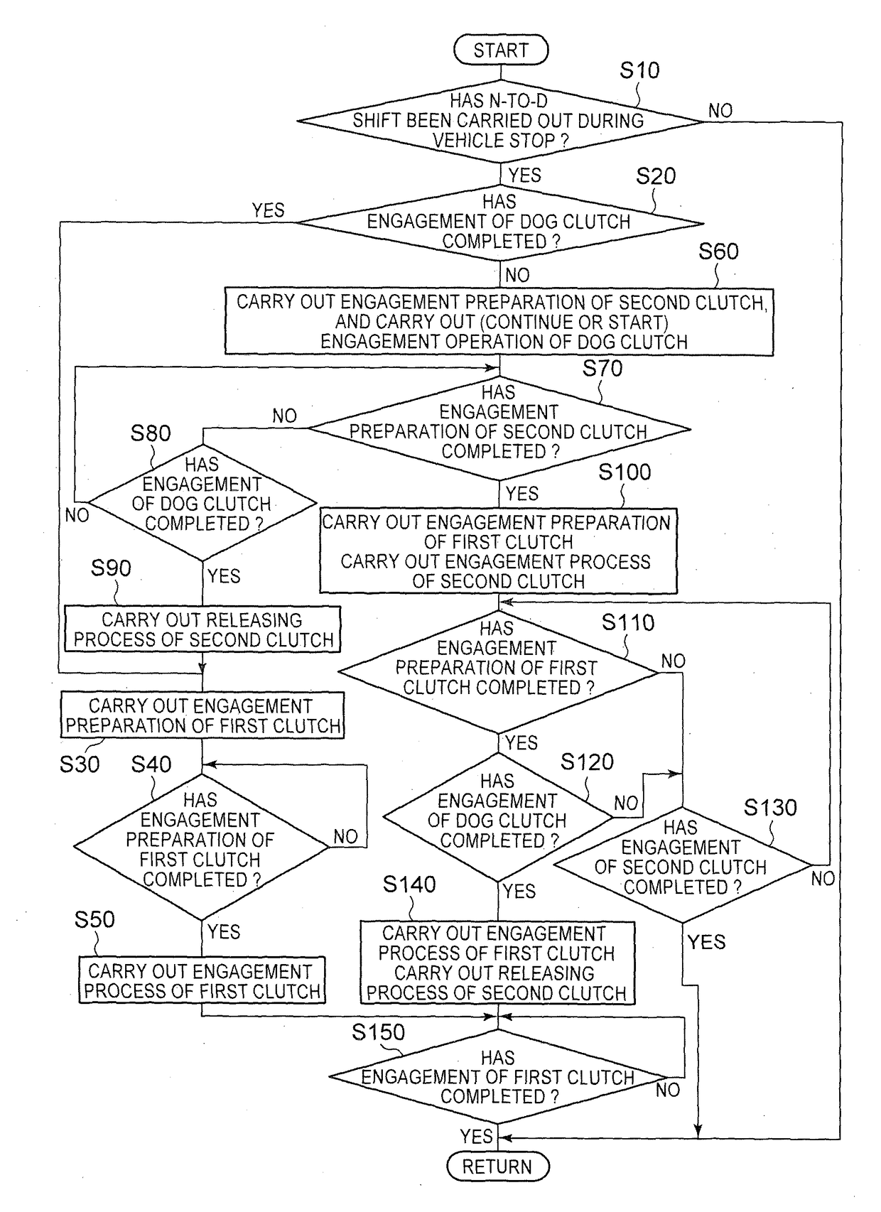
[0051]When an N-to-D shift for operating the shift lever 114 from the neutral position N to the forward drive position D is performed during a stop of the vehicle, it is desirable to establish the first power transmission path PT1 as early as possible such that the vehicle is allowed to immediately start moving. Incidentally, when an engine startup is carried out in advance of the N-to-D shift, there is a possibility that an engagement operation of the dog clutch D1, which is carried out together with an engine startup, has not completed at the time of the N-to-D shift. When the first power transmission path PT1 is established during a stop of the vehicle, it is required to engage the first clutch C1 in a state where engagement of the dog clutch D1 has completed because of the structure of the dog clutch D1. Therefore, when the dog clutch D1 is not engaged at the time of the N-to-D shift after an engine startup during a stop of the vehicle, there is a possibility that the establishm...

second embodiment

[0077]As described above, when the engagement operation of the second clutch C2 is started, the engagement operation of the second clutch C2 is carried out at least until reaching the predetermined state where the second clutch C2 has no torque capacity, so the second clutch C2 is definitely placed in the predetermined state having no torque capacity, and, after the second clutch C2 is placed in the predetermined state, the second clutch C2 is engaged or the engaged clutch is changed by releasing the second clutch C2 and engaging the first clutch C1. Thus, it is possible to suppress a time from the N-to-D shift to the establishment of the second power transmission path PT2 or the first power transmission path PT1.

[0078]The embodiments of the invention are described in detail with reference to the accompanying drawings; however, the invention is also applied to other embodiments.

[0079]For example, in the above-described first and second embodiments, the clutch engagement determinati...


PUM


Abstract

An engagement operation of a dog clutch is carried out while an engagement operation of a second clutch is being carried out, that is, during a situation that an uplock is hard to occur because of a phase shift generated between meshing counterpart members of the dog clutch. Thus, the dog clutch is easily engaged, and it is possible to facilitate preparation for transmission of power through a first power transmission path. If the dog clutch is not engaged, the second clutch is engaged and a second power transmission path is established, so it is possible to start moving a vehicle by transmitting power through the second power transmission path. Thus, when the dog clutch is in a non-engaged state at the time of an N-to-D shift during a stop of the vehicle, it is possible to ensure the startability of the vehicle.

Description

BACKGROUND OF THE INVENTION1. Field of the Invention[0001]The invention relates to a control apparatus for a power transmission system including a plurality of power transmission paths provided in parallel with each other between a driving force source and a drive wheel.2. Description of Related Art[0002]There is well known a power transmission system including a plurality of power transmission paths. The plurality of power transmission paths are provided in parallel with each other between an input rotating member and an output rotating member. Power of a driving force source is transmitted to the input rotating member. The output rotating member outputs the power to a drive wheel. This is, for example, a power transmission system for a vehicle, described in International Application Publication No. 2013 / 176208. International Application Publication No. 2013 / 176208 describes the power transmission system for a vehicle, including a power transmission path through a continuously vari...

Claims


Application Information

Patent Timeline
IPC IPC(8): F16H61/04F16H61/70F16H37/08
CPCF16H61/0403F16H61/702F16H37/0846F16H2312/022F16H2061/0407F16H2061/0474F16H2061/0488F16H37/022F16H61/04B60W30/18054
Inventor INOUE, DAISUKEITO, AKIHIDESAKAMOTO, KAZUYAKONDO, HIROKIFUKAO, MITSUHIROMATSUO, KENJI
Owner TOYOTA JIDOSHA KK
Why Eureka
Try Eureka