Sheet material feeding apparatus and image forming appratus

a feeding apparatus and a technology of image forming, applied in the direction of electrographic process apparatus, thin material handling, instruments, etc., can solve the problems of inability to feed sheet material to a small size, inability to meet the needs of users, and inability to apply unintentional force on the side fence, etc., to achieve the effect of stable feeding of sheet material

Active Publication Date: 2017-11-02
KONICA MINOLTA INC
View PDF0 Cites 0 Cited by
  • Summary
  • Abstract
  • Description
  • Claims
  • Application Information

AI Technical Summary

Benefits of technology

[0008]The present invention has been made in view of the above-described issue, and an object thereof is to provide a downsized sheet material feeding apparatus and an image forming apparatus, capable of suitably changing the force to push up the sheet material in accordance with the size of the sheet material and achieving stable feeding of the sheet material.
[0010]With this configuration, it is possible to easily displace the width regulating member regardless of drawn out / stored states of the cassette with respect to the housing unit, leading to the switching of application and release-application of the biasing force by the push-up plate biasing member, to the posture change of the push-up plate. Moreover, a switching unit exists between the width regulating member and the push-up plate biasing member. This configuration suppresses application of an unintentional force to the width regulating member and stabilizes sheet material feeding performance. Moreover, since the push-up plate displacement, mechanism and the biasing member selecting mechanism are provided on the cassette, it is possible to form the sheet material feeding apparatus relatively in a small size.

Problems solved by technology

Unfortunately, however, the sheet feed cassette described in JP 2015-802 A has a difficulty in engaging the protrusion of the auxiliary push-up plate with the opening of the regulating member unless the cassette is in a state of being completely drawn out from a main body, and this leads to incompatibility with a small-sized sheet having a relatively small width.
This limitation might lead to a concern of extra time and labor on a user.
Another sheet feed apparatus described in JP 2000-53257 A includes the projection on the side fence, that comes in direct contact with the auxiliary pressure lever, leading to a concern of an unintentional force to be applied on the side fence.
This would be a concern of adversely affecting the sheet feed performance.
Furthermore, since a pressure arm, a pressure lever, and an auxiliary pressure lever for upwardly biasing the movable base plate inside a sheet feet tray are provided outside the sheet feed tray, there are concerns of enlargement of the sheet feed apparatus and thus, enlargement of the image forming apparatus.

Method used


Image

  • Sheet material feeding apparatus and image forming appratus
  • Sheet material feeding apparatus and image forming appratus
  • Sheet material feeding apparatus and image forming appratus

Examples


Embodiment Construction

[0040]Hereinafter, an embodiment of the present invention will be described with reference to the drawings, However, the scope of the invention is not limited to the illustrated examples.

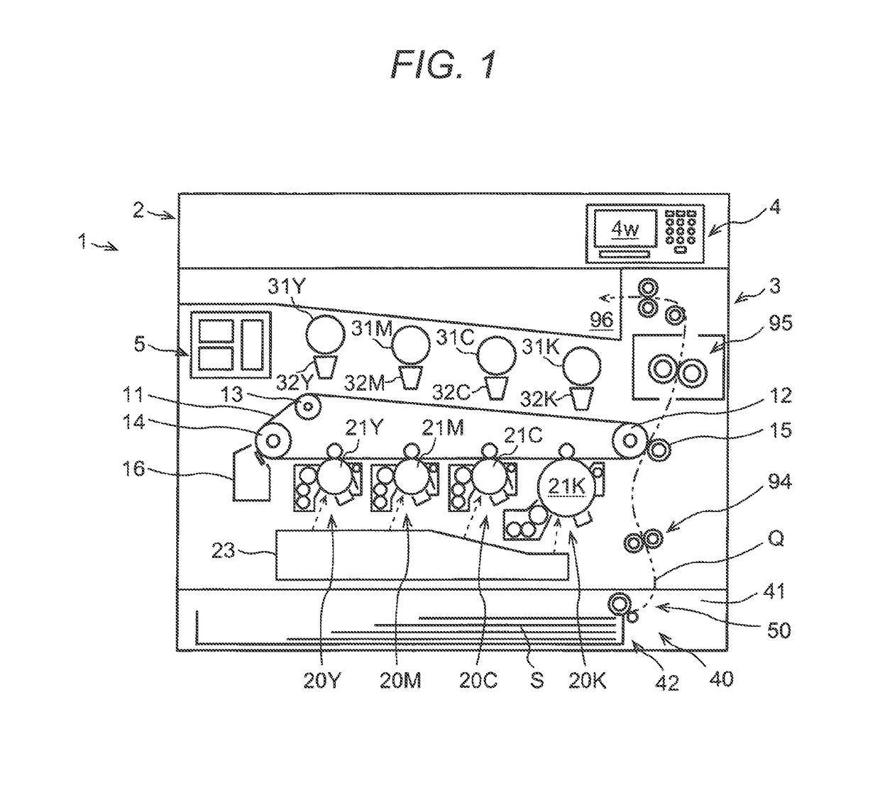
[0041]First, an outline of the structure of an image forming apparatus according to an embodiment of the present invention will be described with reference to FIG. 1, together with image output operation. FIG. 1 is a partial vertical cross-sectional front view of the image forming apparatus. Note that an arrowed two-dot chain line in the diagram indicates a conveyance path and a conveyance direction of the sheet material.

[0042]An image forming apparatus 1 is a tandem type color copier as illustrated in FIG. 1, including an image reading unit 2, a printing unit 3, an operation unit 4, and a main control unit 5. The image reading unit 2 reads an image of a document. The printing unit 3 prints the read image on a sheet material such as a sheet of paper. The operation unit 4 is used to input print condi...


PUM


Abstract

A sheet material feeding apparatus includes: a cassette configured to internally contain a sheet material; a push-up plate that is mounted on an inner bottom surface of the cassette and that is a plate on top surface of which the sheet material is mounted; a push-up plate displacement mechanism configured to include push-up plate biasing members and to change a posture of the push-up plate using a biasing force of one of the push-up plate biasing members; a width regulating member configured to be displaced in a width direction intersecting with a feeding direction and to regulate a position of the sheet material; and a biasing member selecting mechanism that includes a switching unit configured to switch application and release-application of the biasing force of one of the push-up plate biasing members to a posture change of the push-up plate, in interlocking with displacement of the width regulating member.

Description

[0001]The entire disclosure of Japanese Patent Application No. 2016-092307 filed on May 2, 2016 including description, claims, drawings, and abstract are incorporated herein by reference in its entirety.BACKGROUND OF THE INVENTIONField of the Invention[0002]The present invention relates to a sheet material feeding apparatus and an image forming apparatus including the same.Description of the Related Art[0003]An image forming apparatus such as a copier, a printer, and a facsimile includes a sheet material feeding apparatus that feeds a sheet material such as a sheet of paper. In some cases, the sheet material feeding apparatus includes a push-up plate that pushes up a downstream section of the sheet in a feeding direction in order to allow a top layer of the plurality of sheet materials stacked in a container unit to come in contact with a feed roller from below. There is a proposed technique capable of changing a force to push up the push-up plate in accordance with the size of the ...

Claims


Application Information

Patent Timeline
Patent Type & Authority Applications(United States)
IPC IPC(8): G03G15/00B65H1/14B65H1/26B65H9/04
CPCG03G15/6529B65H1/266B65H2801/06B65H9/04B65H1/14B65H1/12B65H2405/111B65H2511/12B65H2515/30G03G15/6502G03G15/6511B65H2220/01B65H2220/02B65H9/08
Inventor KURODA, YOSHITAKATANIMOTO, HIROSHISUZUKI, YASUHIRO
Owner KONICA MINOLTA INC
Why Eureka
Try Eureka