Boring Head With A Mechanism For Clamping A Displaceable Tool Carrier

a technology of displaceable tools and clamping mechanisms, which is applied in the direction of turning apparatuses, turning machines accessories, metal-working apparatus, etc., can solve the problems of insufficient force of the displacement motor itself at rest, time-consuming and often imprecise manual adjustments, and still requires manual handling and an interruption of boring operation

Pending Publication Date: 2022-07-14
BIG KAISER PRAZISIONSWERKZEUGE AG
View PDF1 Cites 0 Cited by
  • Summary
  • Abstract
  • Description
  • Claims
  • Application Information

AI Technical Summary

Problems solved by technology

Manual adjustments, however, are time-consuming and often imprecise.
The electric actuator, however, represents an external device which still requires manual handling and an interruption of the boring operation.
A challenge with tool carriers that can be displaced by means of a motor represents in particular their fixation within the tool body during the boring operation.
The force of the displacement motor itself a

Method used


Image

  • Boring Head With A Mechanism For Clamping A Displaceable Tool Carrier
  • Boring Head With A Mechanism For Clamping A Displaceable Tool Carrier
  • Boring Head With A Mechanism For Clamping A Displaceable Tool Carrier

Examples


first embodiment

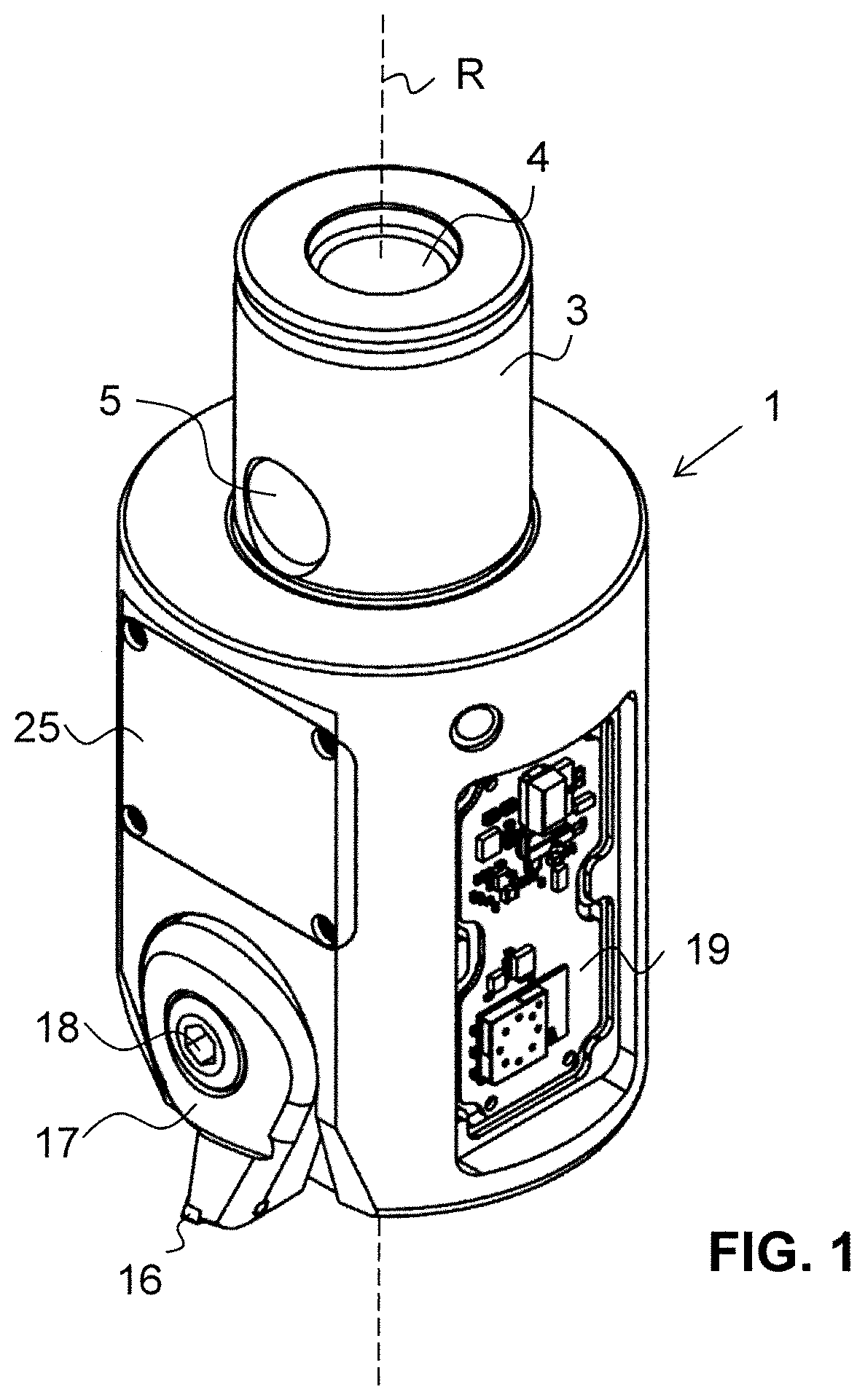
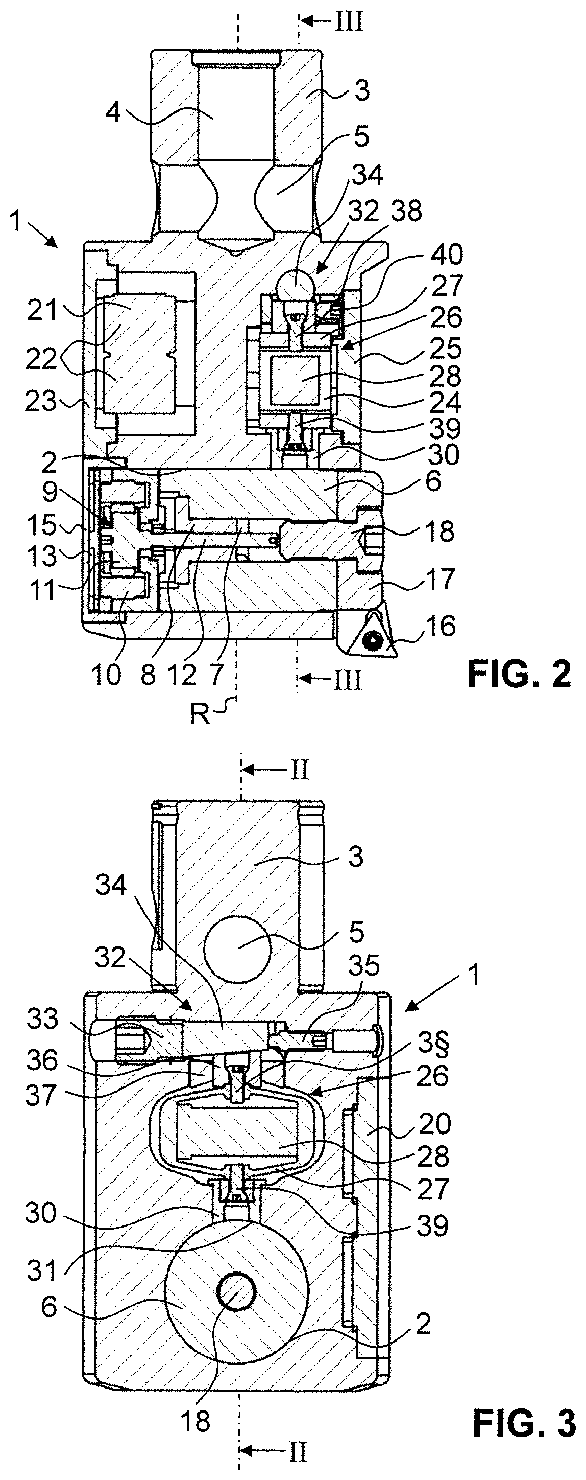
[0076]As shown in FIG. 1, a preferred boring head comprises a tool body 1 of essentially cylindrical form. Attached to the tool body 1 and made in one piece therewith is a fastening peg 3. The fastening peg 3 also has a cylindrical form, but with a smaller diameter than the tool body 1. The fastening peg 3 has a central longitudinal bore 4 and a transversal bore 5 which intersects the longitudinal bore 4. The boring head is adapted to be fastened to a boring machine by means of the fastening peg in a manner as known to the skilled person. During a boring operation, a rotating motion is transmitted from the boring machine to the boring head which, as a result, rotates about a main rotation axis R. The main rotation axis R also forms the central longitudinal axis of the cylindrical form of the tool body 1.

[0077]In the region towards the end face of the tool body 1 that is directed away from the fastening peg 1, the tool body 1 comprises a transversal opening 2 (see FIG. 2). The transv...

second embodiment

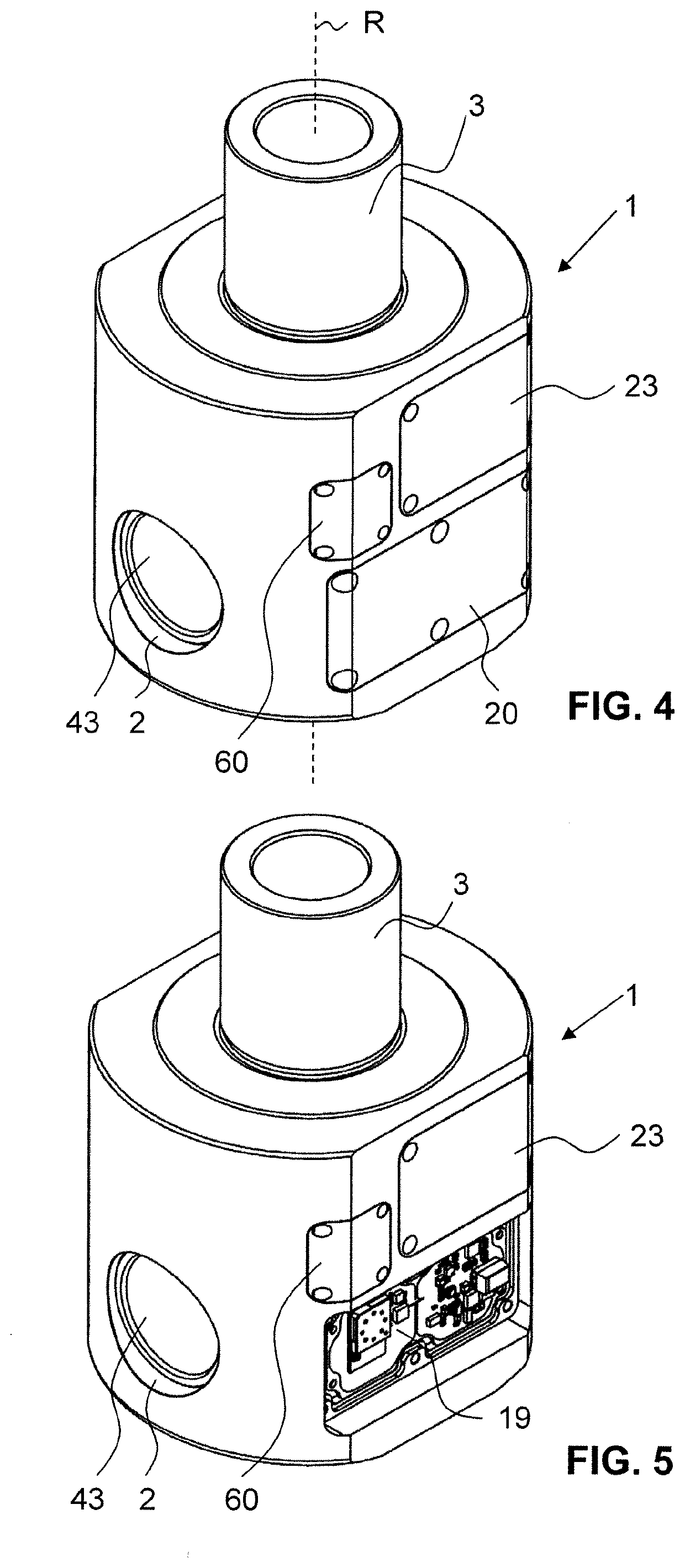
[0091]an inventive boring head is shown in FIGS. 4 to 8 which is described in the following.

[0092]In comparison to the embodiment of FIGS. 1 to 3, the one of FIGS. 4 to 8 is adapted for the machining of bores with a smaller diameter.

[0093]As can be seen from FIGS. 4 to 8, the boring head according to this embodiment also comprises a tool body 1 with a fastening peg 3 and a transversal opening 2 in which a radially displaceable, cylindrical tool carrier 6 is arranged. In contrast to the embodiment of FIGS. 1 to 3, the cutting tool is here not attached to an end face of the tool carrier 6, but via a tool holder to a tool attachment bore 41 which extends along the main rotation axis R through the tool carrier 6 (see FIG. 6). Please note that the tool holder and the cutting tool are not shown in FIGS. 4 to 8. For this purpose, the tool holder comprises a cylindrical, rod-shaped part which is introduced into the tool attachment bore 41 through a central opening provided on the side of th...

third embodiment

[0109]an inventive boring head is shown in FIGS. 9 and 10. While the principle for displacing the tool carrier 6 relative to the tool body 1 is similar as the one of the embodiment shown in FIGS. 1-3, the principle of the clamping mechanism 26 is similar as the one of the embodiment shown in FIGS. 4-8.

[0110]As can be seen in FIG. 9, the tool carrier 6 comprises a tool attachment bore 41 which extends along the main rotation axis R and serves for the attachment a rod-shaped tool holder with a cutting tool. For transversally displacing the tool carrier 6, a motor 9 with a stator 10 and a rotor 11 is arranged within the transversal opening 2 of the tool body 1 near an end face of the tool carrier 6. A nut 8 with an inner thread is fixed in a torque proof manner within a central bore of the tool carrier 6. As in the embodiment of FIGS. 1-3, the rotational motion of the motor 9 is transferred into a radial displacement of the tool carrier 6 via a threaded drive shaft that engages with th...


PUM


Abstract

A boring head is provided comprising a tool body (1) having a main rotation axis (R) about which the tool body (1) rotates during boring operations. The boring head further comprises a tool carrier (6) arranged in or on the tool body (1), a first motor (9) for displacing the tool carrier (6) relative to the tool body (1) and a clamping mechanism (26) with a clamping element (27, 55, 68, 81) for effecting a clamping force on the tool carrier (6), in order to prevent a displacement of the tool carrier (6) relative to the tool body (1) during boring operations. The clamping mechanism (26) is an active clamping mechanism which effects a clamping force that can be adjusted actively.

Description

CROSS-REFERENCE TO RELATED APPLICATIONS[0001]The present application is a national phase entry under 35 U.S.C. § 371 of International Application No. PCT / EP2020 / 064816, filed on May 28, 2020 which claims priority from European Patent Application No. 19177207.8 filed on May 29, 2019, the disclosure of which is incorporated herein by reference.TECHNICAL FIELD[0002]The present invention relates to a boring head with a clamping mechanism for clamping a displaceable tool carrier, in order to prevent a displacement of the tool carrier relative to a tool body during boring operations.PRIOR ART[0003]Boring heads which are used for example for chip forming metal cutting often comprise a tool carrier which is radially displaceable with respect to a tool body, in order to allow a radial adjustment of the cutting tool attached to the tool carrier. Such boring heads are for example used for enlarging an already existing hole by means of rotating the boring head with the cutting tool attached the...

Claims


Application Information

Patent Timeline
IPC IPC(8): B23B29/034
CPCB23B29/03414B23B2260/108B23B2229/16B23B29/03
Inventor FENOLLOSA CLIMENT, JOSE MARIATHALMANN, LUKASMARTIN, MANUELROHRER, PASCALSTÜSSI, CHRISTOPH
Owner BIG KAISER PRAZISIONSWERKZEUGE AG
Why Eureka
Try Eureka