Unlock instant, AI-driven research and patent intelligence for your innovation.
Spacer member
What is Al technical title?
Al technical title is built by PatSnap Al team. It summarizes the technical point description of the patent document.
a spacer and member technology, applied in the field of spacer members, can solve the problems of spacer members being displaced or damaged, glass sheets may suffer damage,
Inactive Publication Date: 2017-09-21
NIPPON SHEET GLASS CO LTD
View PDF5 Cites 1 Cited by
Summary
Abstract
Description
Claims
Application Information
AI Technical Summary
This helps you quickly interpret patents by identifying the three key elements:
Problems solved by technology
Method used
Benefits of technology
Benefits of technology
The patent text discusses a problem that occurs when using a spacer member with a curved convex face in contact with a glass sheet. This can cause damage to the glass sheet or spacer member due to compressive stress caused by atmospheric pressure. Additionally, the curved convex face of the spacer member can cause the spacer member to roll over and become easily displaced when the spacer member is moved between glass sheets. The patent aims to address this problem by providing a new design for the spacer member that reduces the risk of damage and displacement during use.
Problems solved by technology
As a result, the spacer members may be displaced or damaged, and even the glass sheet may suffer damage if a load is concentrated on a local part of the glass sheet.
Method used
Image
Click on the blue label to locate the original text in one second.
Reading with bidirectional positioning of images and text.
Examples
first embodiment
Modifications of Spacer
[0064]Modifications of the spacer 3 according to the first embodiment will be described hereinafter in reference to FIG. 9.
[0065]FIG. 9 shows four types of spacer 3, i.e., Type A to Type D.
[0066]Type A has a plurality of contacting members 7 connected to each other through projecting pieces 8 extending integrally from the contacting members 7, respectively, while the projecting pieces 8 being converged at a central portion of the spacer 3.
[0067]Type B has a plurality of contacting members 7 connected to each other in an annular shape, in which the contacting members 7 that are circumferentially adjacent to each other are connected to each other by a projecting piece 8.
[0068]Type C has a combination of the projecting pieces 8 extending integrally from the contacting members 7, which forms a ring-like connection part 11, in which the plurality of contacting members are accommodated.
[0069]Type D has a plurality of projecting pieces 8 extending inward from a ring-...
second embodiment
[0078]Referring to FIGS. 10 and 11, a spacer 3 has one contacting member 7. A ring part 9 is provided to surround the contacting member 7, and is supported by projecting pieces 8 extending integrally from the contacting member 7.
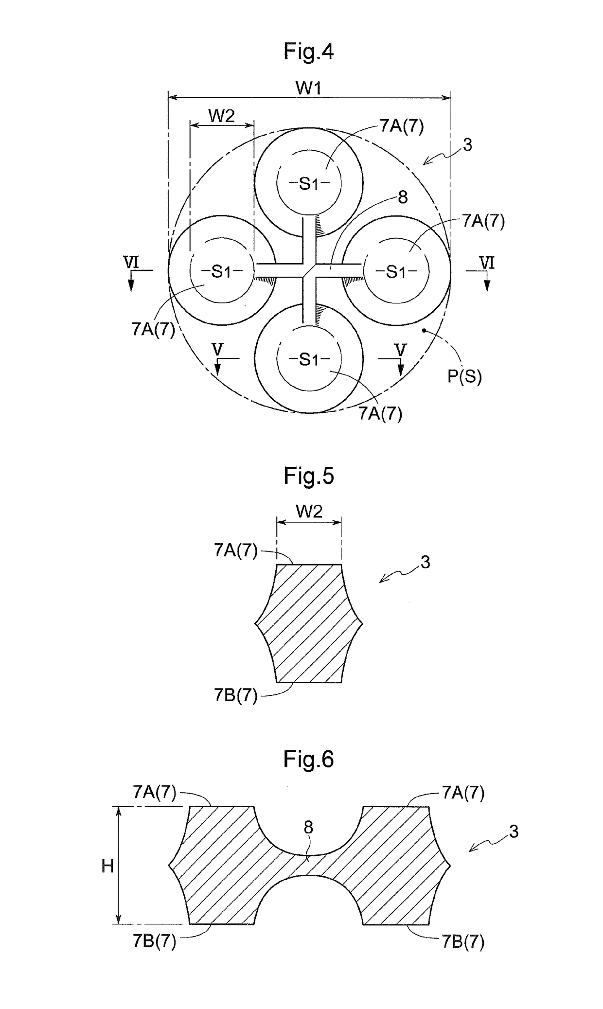
[0079]According to the second embodiment, on the assumption that an imaginary column P that circumscribes the spacer 3 is provided, an area S1 of a first planar part 7A (an area S1 of a second planar part 7B) is equal to or smaller than one quarter of a circular cross section S of the column P along the planar direction of the glass sheet 1.
[0080]In the arrangement shown in FIG. 10, a maximum width dimension W2 of the first planar part 7A is equal to or smaller than one half of a maximum width dimension W1 of the spacer 3. As a result, the area S1 of the first planar part 7A is equal to or smaller than one quarter of a cross section S of the first planar part 7A.
[0081]In the contacting member 7, a maximum width dimension W2 of the first planar part 7A or the...
PUM
Property
Measurement
Unit
Mass
aaaaa
aaaaa
Shape
aaaaa
aaaaa
Area
aaaaa
aaaaa
Abstract
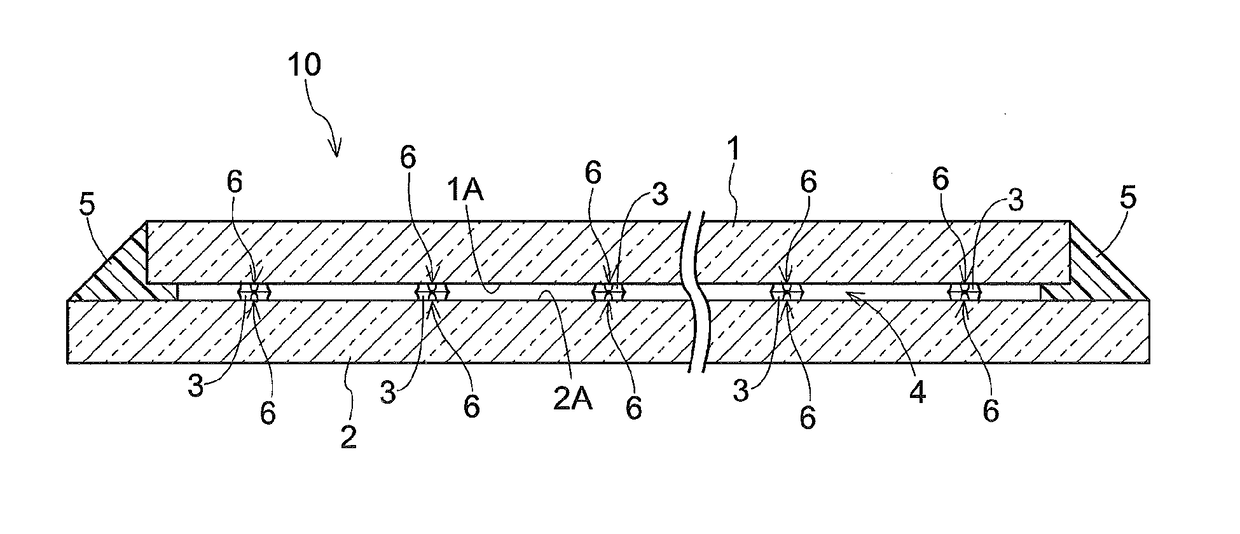
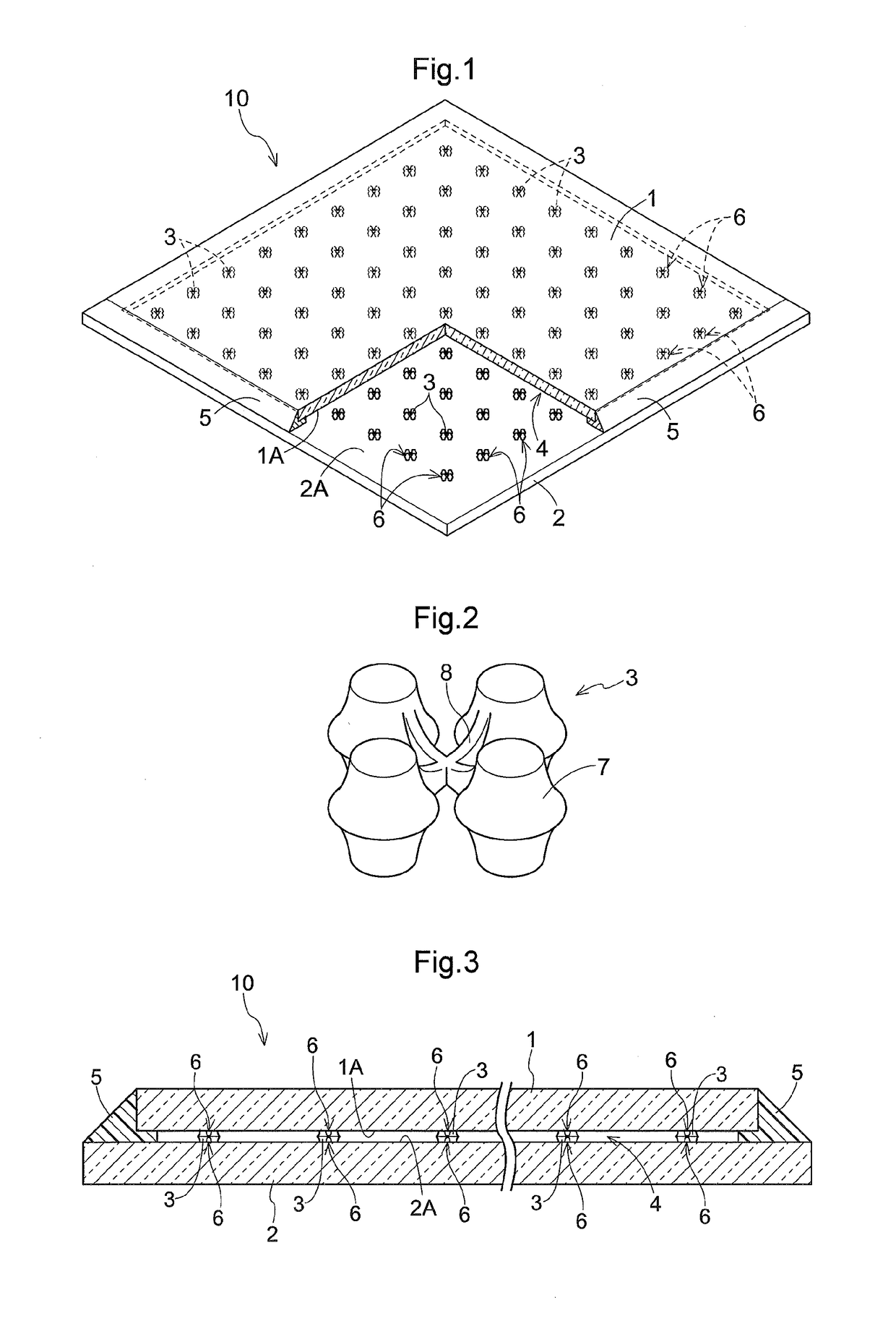
The spacer member being disposed at each of support points set at predetermined intervals on opposing faces of a pair of glass sheets opposing to each other when a gap formed between the pair of glass sheets is maintained under a depressurized state, wherein the spacer member includes: at least one contacting member having a first planar part on one side and a second planar part on the other side coming into contact with the respective opposing faces of the glass sheets, and a projecting piece extending integrally from the contacting member, and on the assumption that an imaginary column that circumscribes the spacer member with its height direction being vertical to the first planar part is provided, the total area of the first planar part or the total area of the second planar part is equal to or smaller than one half of a circular cross section of the column.
Description
TECHNICAL FIELD[0001]The present invention relates to a plurality of spacer members for a glass panel disposed between a pair of glass sheets when a vacuum double glazing glass panel is manufactured.BACKGROUND ART[0002]In a vacuum double glazing glass panel (simply referred to as “glass panel” hereinafter) in which peripheries of a pair of glass sheets are sealed to establish a depressurized state, a compressive force is applied from the outside of the glass sheets by atmospheric pressure. Therefore, spacer members having high compressive strength are arranged at regular intervals between the pair of glass sheets. When an external force such as a shock or a wind is applied to the glass panel, the glass panel is bent to cause the pair of glass sheets to move relatively to each other in a plane direction. As a result, the spacer members may be displaced or damaged, and even the glass sheet may suffer damage if a load is concentrated on a local part of the glass sheet.[0003]In view of ...
Claims
Application Information
Patent Timeline
Application Date:The date an application was filed.
Publication Date:The date a patent or application was officially published.
First Publication Date:The earliest publication date of a patent with the same application number.
Issue Date:Publication date of the patent grant document.
PCT Entry Date:The Entry date of PCT National Phase.
Estimated Expiry Date:The statutory expiry date of a patent right according to the Patent Law, and it is the longest term of protection that the patent right can achieve without the termination of the patent right due to other reasons(Term extension factor has been taken into account ).
Invalid Date:Actual expiry date is based on effective date or publication date of legal transaction data of invalid patent.

