Eureka AIR delivers breakthrough ideas for toughest innovation challenges, trusted by R&D personnel around the world.

Network function virtualization

a network function and virtualization technology, applied in the field of network function virtualization, can solve problems such as inability to meet constraints, problems that may be compounded, and cannot be achieved

Active Publication Date: 2017-11-09
HEWLETT-PACKARD ENTERPRISE DEV LP
View PDF1 Cites 41 Cited by
  • Summary
  • Abstract
  • Description
  • Claims
  • Application Information

AI Technical Summary

Benefits of technology

The patent describes a method for implementing network function virtualization, which aims to consolidate multiple network equipment types onto standardized hardware. This approach allows for the dynamic movement of virtual network functions to different locations in the network without the need for physical installation of new hardware. The method involves a three-stage process of definition, instantiation, and assignment of virtual network functions. The patent also provides a diagrammatic representation of the data model used for implementing virtual network functions. The technical effects of this approach include improved efficiency and flexibility in network operations, reduced latency, and better resource utilization.

Problems solved by technology

This comparative case can lead to problems as it may not be possible to ensure that an internal representation or instance meets any required constraints and at the same time may be implemented in a given physical environment.
These problems may be compounded if several provisioning requests are being processed in parallel.
In these cases the constraints cannot be met.
Also in some cases, the first two virtual machines may be able to be assigned resources that meet the constraints but it may not be possible to do this for the third virtual machine, requiring a rollback of the reservation of resources for the first two virtual machines.
This can be costly in terms of time and physical computing resources.
For example, if it is discovered that three virtual machines cannot be instantiated then time need not be spent looking for appropriate resources.
If the state of the physical computing resources indicate this is not available then resources are not available and a request to provision the virtual network function cannot be met, e.g. may be declined.
This may be found to need scaling up due to load demands.

Method used


Image

  • Network function virtualization
  • Network function virtualization
  • Network function virtualization

Examples


Embodiment Construction

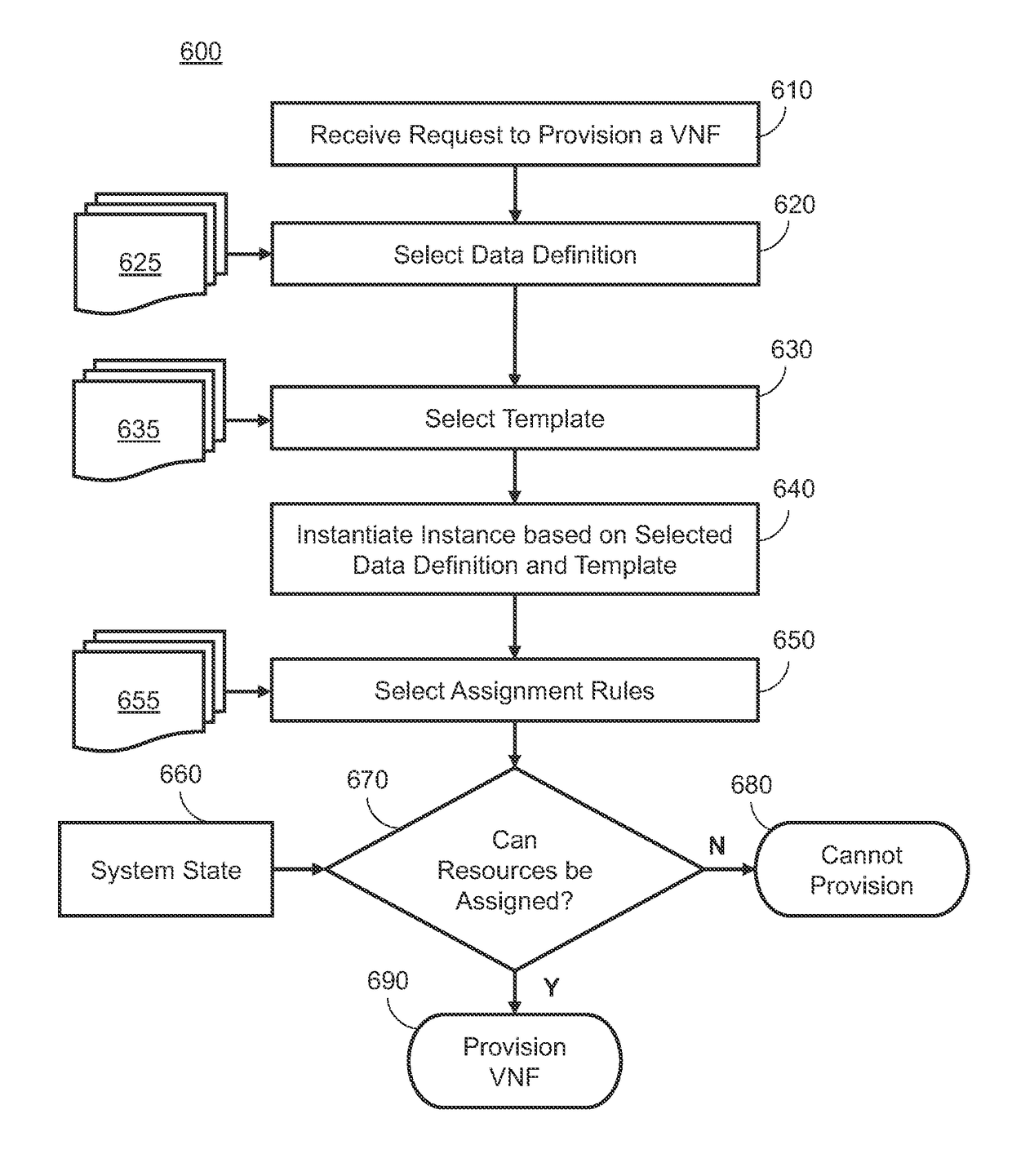
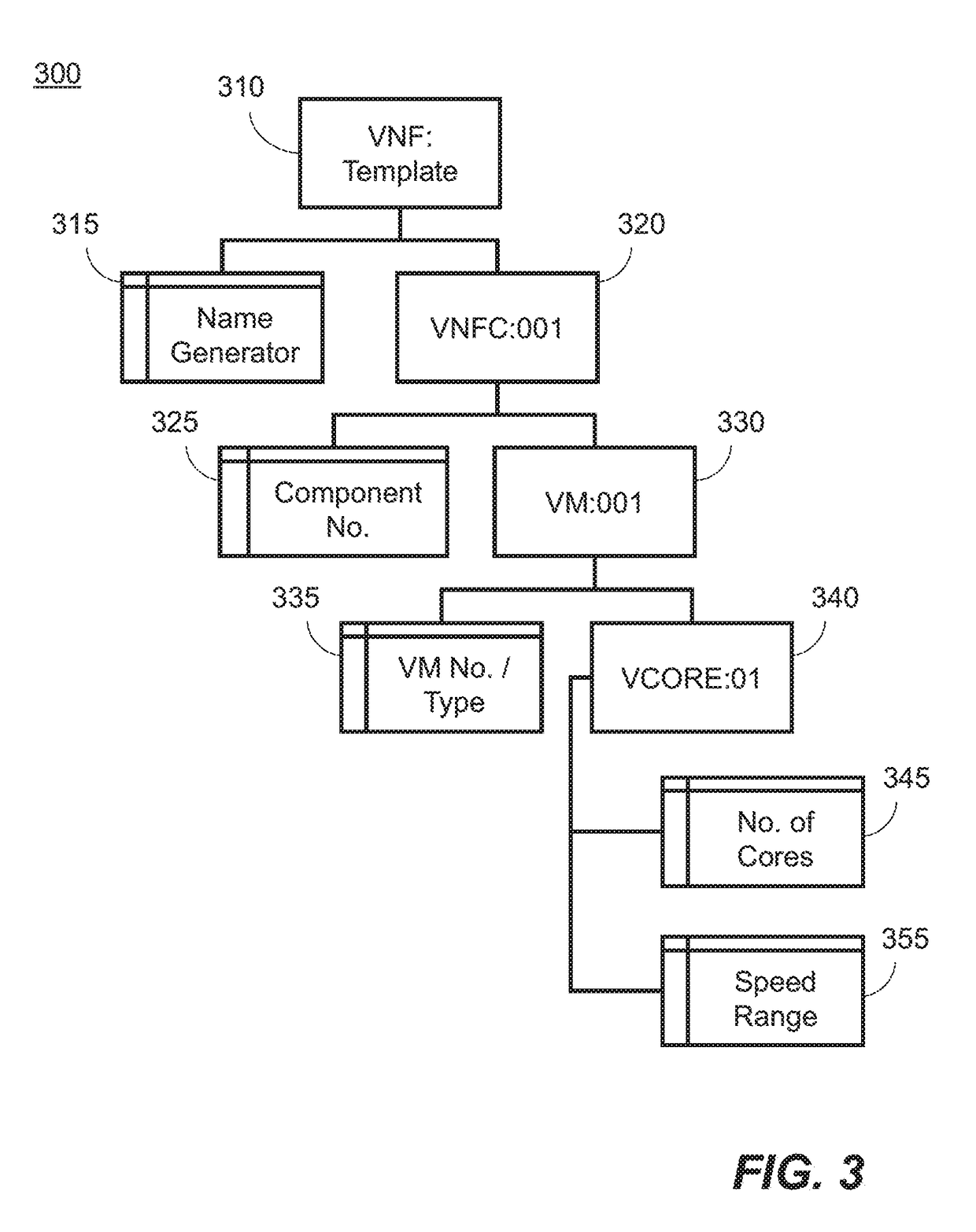
[0011]Certain examples described herein provide a method to provide network function virtualization, sometimes referred to in the art as “on-boarding”. Certain examples described herein provide a three stage process of definition, instantiation and assignment to implement a virtual network function. In certain cases this enables a virtual network function to be implemented using a combination of virtual machines and physical servers, as well as enabling virtual network functions to be composed of other virtual network functions in turn. It may also allow guaranteed exclusivity for defined resources, such as network bandwidth.

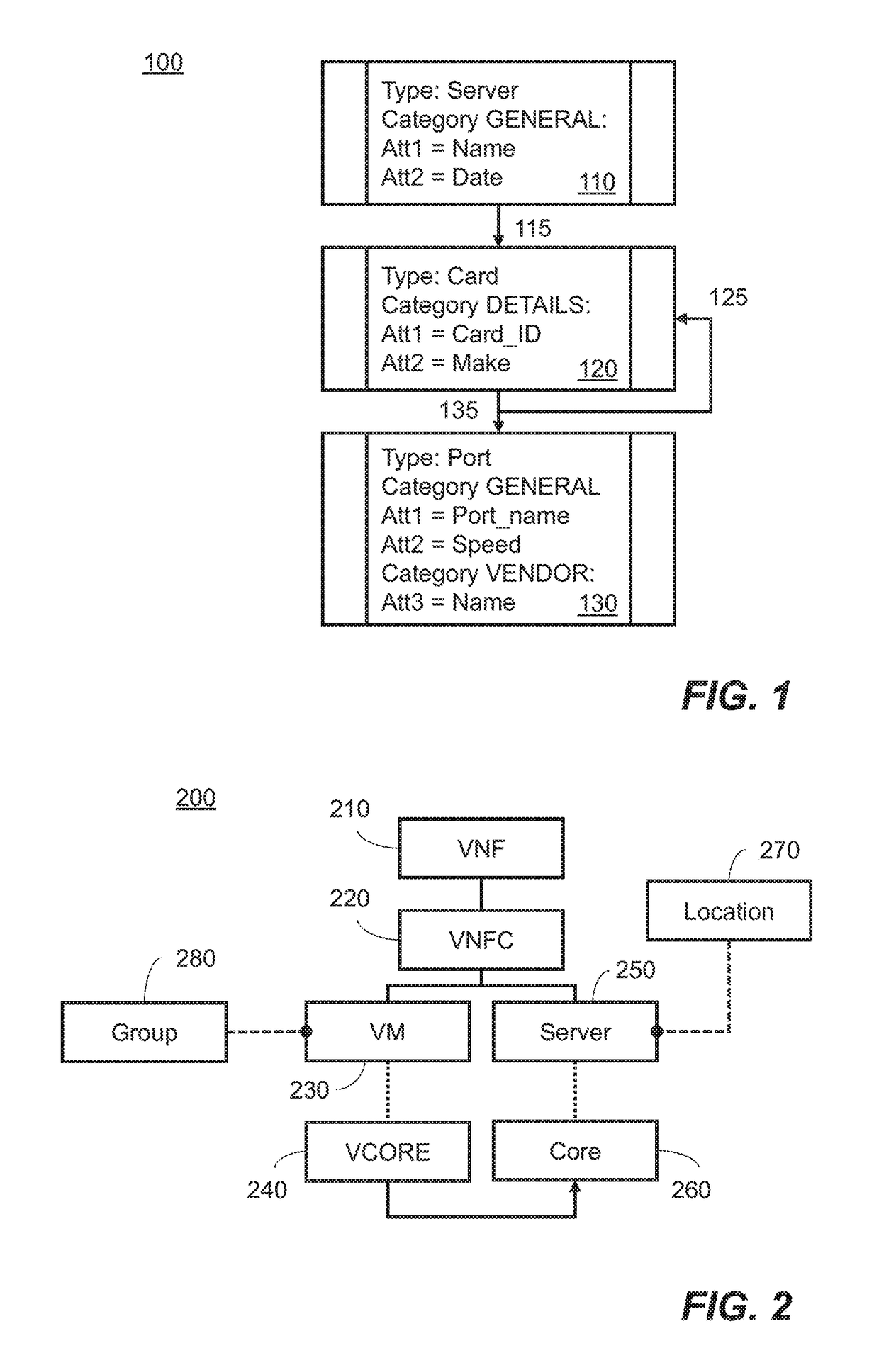
[0012]FIG. 1 shows components of a first data definition for implementing a virtual network function according to an example. The components have been derived from a data model. The data model may be used to define one or more of a data definition, a template and an instance of a virtual network function. The data model uses two model components. In one implemen...


PUM


Abstract

Examples for network function virtualization are described. These examples include accessing definition data defining a virtual network function, the virtual network function comprising one or more components. The definition data is then instantiated to generate an instance of the virtual network function. Physical computing resources may then be assigned to the instance of the virtual network function.

Description

BACKGROUND[0001]Network function virtualization is an emerging design approach for constructing Information Technology applications, particularly in the telecommunications industry. The classical approach to network architecture is based upon fragmented, purpose built hardware for implementing network functions—also known as physical network functions (e.g. firewalls, deep packet inspectors, network address translators) which require physical installation at every site at which they are needed. In contrast, network function virtualization aims to consolidate many network equipment types onto, for example, standardised high volume servers, switches, and storage through the implementation of virtual network functions in software which can run on a range of standard hardware. Furthermore, network function virtualization aims to transform network operations because the virtual network functions can be dynamically moved to, or instantiated in, various locations in the network as required...

Claims


Application Information

Patent Timeline
Patent Type & Authority Applications(United States)
IPC IPC(8): H04L12/24H04L29/08G06F9/445
CPCH04L41/0806H04L41/0893H04L41/00G06F9/445H04L67/34H04L41/40H04L41/0894H04L41/0895
Inventor PEREZ, IGNACIO ALDAMAGIRON, RUBEN SEVILLAKINCL, NORMAN
Owner HEWLETT-PACKARD ENTERPRISE DEV LP
Why Eureka
Eureka Blog
Learn More