Method and system of virtual machine migration

a technology of virtual machines and migration methods, applied in data switching networks, multi-programming arrangements, instruments, etc., can solve the problems of inability to directly apply these techniques, and inability to implement power saving in cooperation between data centers and networks

Active Publication Date: 2013-03-12
HITACHI LTD
View PDF10 Cites 61 Cited by
  • Summary
  • Abstract
  • Description
  • Claims
  • Application Information

AI Technical Summary

Benefits of technology

[0031]As described above and according to the present invention, it is possible to decrease a downtime in live migration over a wide area network. Hence, VMs that are active in running various applications can be migrated over a wide area. Consequently, the present invention provides the advantageous effects of enabling the implementation of power saving mentioned as the first object thereof, the implementation of load distribution mentioned as the second object thereof, and the implementation of fault countermeasure processing mentioned as the third object thereof.
of enabling the implementation of power saving mentioned as the first object thereof, the implementation of load distribution mentioned as the second object thereof, and the implementation of fault countermeasure processing mentioned as the third object thereof.

Problems solved by technology

It is not possible to apply these techniques directly to actual practice of VM migration between servers that are located distributively in a wide area, i.e., the implementation of power saving in cooperation between each data center and network is not feasible with these techniques.
However, the method described in the Patent Document 2 is disadvantageous in that the flows of communication traffic tend to concentrate on a path to a particular data center even in cases where data centers are located distributively.

Method used


Image

  • Method and system of virtual machine migration
  • Method and system of virtual machine migration
  • Method and system of virtual machine migration

Examples


first preferred embodiment

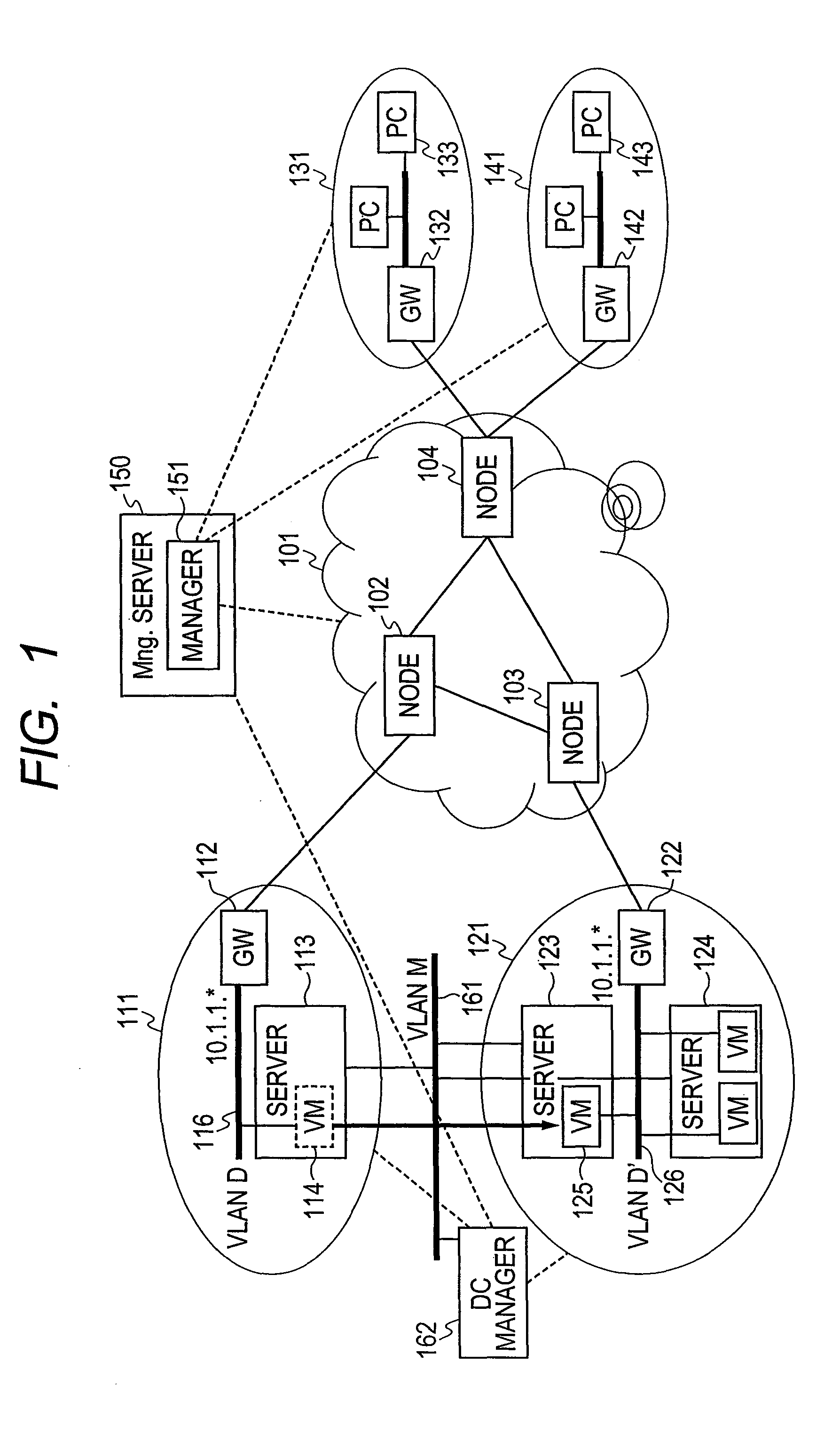
[0045]FIG. 1 is a physical configuration diagram of a network in exemplary implementation common to first and second preferred embodiments of the present invention.

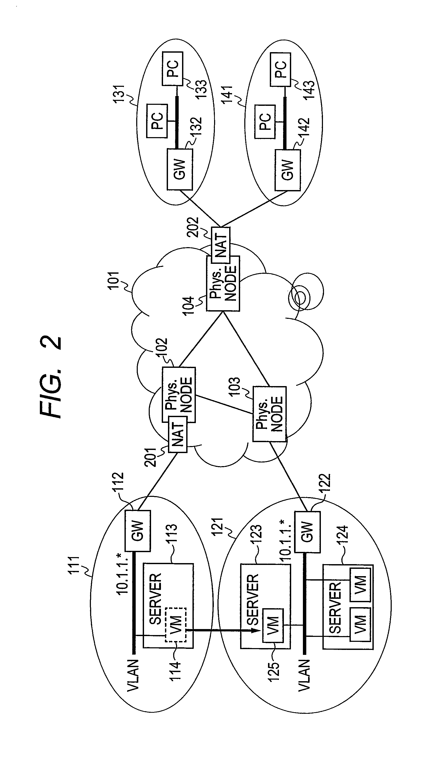
[0046]As shown in FIG. 1, a first central network WAN 101 includes an edge node 102 connected to a data center 111, an edge node 103 connected to a data center 121, and an edge node 104 connected to user networks 131 and 141 configuring a second network. The WAN 101 may include more network nodes, and plural network nodes may be connected to different user networks. In the first preferred embodiment of the present invention, the edge nodes 102, 103, and 104 are routers each having a function for network address translation (NAT). In the second preferred embodiment to be described later, the edge nodes 102, 103, and 104 are level-3 (L3) switches each having a function for network virtualization.

[0047]In the WAN 101, the edge nodes thereof may be interconnected via a core node instead of direct interconnection therebetween....

second preferred embodiment

[0105]The following describes an overview of the second preferred embodiment of the present invention with reference to FIG. 6. In the second preferred embodiment shown in FIG. 6, the WAN 101 is virtualized to provide two virtual networks 601A and 601B. These virtual networks are arranged to have a topology equivalent to that of the physical network 101. More specifically, the virtual network 601A includes a virtual node 602A corresponding to the physical node 102, a virtual node 603A corresponding to the physical node 103, and a virtual node 604A corresponding to the physical node 104. Likewise, the virtual network 601B includes a virtual node 602B corresponding to the physical node 102, a virtual node 603B corresponding to the physical node 103, and a virtual node 604B corresponding to the physical node 104.

[0106]A packet on the virtual network 601A and a packet on the virtual network 601B can coexist actually on the physical network 101. By an identifier of each packet, a wavelen...


PUM


Abstract

In cooperation between each data center and a WAN, virtual machine migration is carried out without interruption in processing so as to enable effective power-saving implementation, load distribution, or fault countermeasure processing. Each node located at a boundary point between the WAN and another network is provided with a network address translation (NAT) function that can be set dynamically to avoid address duplication due to virtual machine migration. Alternatively, each node included in the WAN is provided with a network virtualization function; and there are implemented a virtual network connected to a data center for including a virtual machine before migration, and a virtual network connected to a data center for including the virtual machine after migration, thereby allowing coexistent provision of identical addresses. Thus, the need for changing network routing information at the time of virtual machine migration can be eliminated, and a setting change for migration accomplished quickly.

Description

CLAIM OF PRIORITY[0001]The present application claims priority from Japanese patent application JP2010-077436 filed on Mar. 30, 2010, the content of which is hereby incorporated by reference into this application.BACKGROUND OF THE INVENTION[0002]The present invention relates to a technique for live migration of virtual machines among servers located at different network points.[0003]As the amount of communication traffic on the Internet has been increasing, the amount of power consumption in terms of entire networking has also been growing continuously. Meanwhile, the significance of power saving is becoming higher in the efforts of solving the global warming issue including suppression of carbon dioxide emissions. Although a certain level of power saving has been accomplished in individual data centers and network nodes by using conventional techniques, it is of critical importance at present that each data center and a wide area network (WAN) should be arranged to work cooperative...

Claims


Application Information

Patent Timeline
Patent Type & Authority Patents(United States)
IPC IPC(8): G06F15/173G06F9/46G06F9/50G06F11/20
CPCG06F9/4856H04L12/4641H04L29/12028H04L29/12264H04L29/12367H04L45/00H04L49/557H04L49/70H04L61/103H04L61/2046H04L61/2514G06F11/1484Y02B60/144Y02B60/162Y02D10/00H04L61/5046H04L45/76
Inventor KANADA, YASUSIKASUGAI, YASUSHISUZUKI, SHINJITARUI, TOSHIAKI
Owner HITACHI LTD
Why Eureka
Try Eureka