Electric front derailleur

a technology of front derailleur and electric drive, which is applied in the direction of chain/belt transmission, vehicle components, cycle equipment, etc., can solve problems such as slipping or inaccurate transmission

Active Publication Date: 2017-11-23
TIEN HSIN INDS
View PDF0 Cites 11 Cited by
  • Summary
  • Abstract
  • Description
  • Claims
  • Application Information

AI Technical Summary

Benefits of technology

[0006]The main objective of the present disclosure is to provide an electric front derailleur, which can prevent the problem of a stuck failure or inaccuracy from occurring during a gear shift when the bicycle is subject to an impact or vibration during a ride.
[0017]Thus, if the chain guide is subject to an impact while a bicycle is being ridden on a road, the impact force is first transferred to the chain guiding portion, and the chain guiding portion transfers the impact force to the first side wall and the second side wall through the pivot portion, to achieve a first buffering effect to reduce the vibration force; then, the force is transferred by the first side wall and the second side wall to the swing member, the internal gear of the swing member absorbs a part of the impact force to buffer the impact force, the remaining impact force attenuates sequentially through the linking member, the rack, the transmission gear, and the first transmission member, and finally, the worm gear absorbs the remaining weak impact force, thereby preventing the problem of a stuck failure or inaccurate chain guiding function from occurring during a gear shift when the bicycle is subject to an impact or vibration during a ride.

Problems solved by technology

However, during a ride on a road and particularly in the mountainous area or suburbs, it is difficult for the bicycle to avoid an uneven road and thus bounce, and the front fork unit 5, the swing arm 6, and the linking member 6a are all possibly impacted by hard objects, causing the swing arm 6 to be dislocated, and thus the worm gear 29 is tightly stuck by the worm gear 31, making the actuating device 12 unable to drive the worm gear 29 to rotate freely and thus become damaged, thereby causing the problem of a stuck failure or inaccurate transmission during a gear shift operation.

Method used


Image

  • Electric front derailleur
  • Electric front derailleur
  • Electric front derailleur

Examples


Embodiment Construction

[0027]The detailed content and technical illustration of the present disclosure are provided through embodiments, but it should be understood that the embodiments are only intended for exemplary illustration and not to be interpreted as a limit to implementation of the present disclosure.

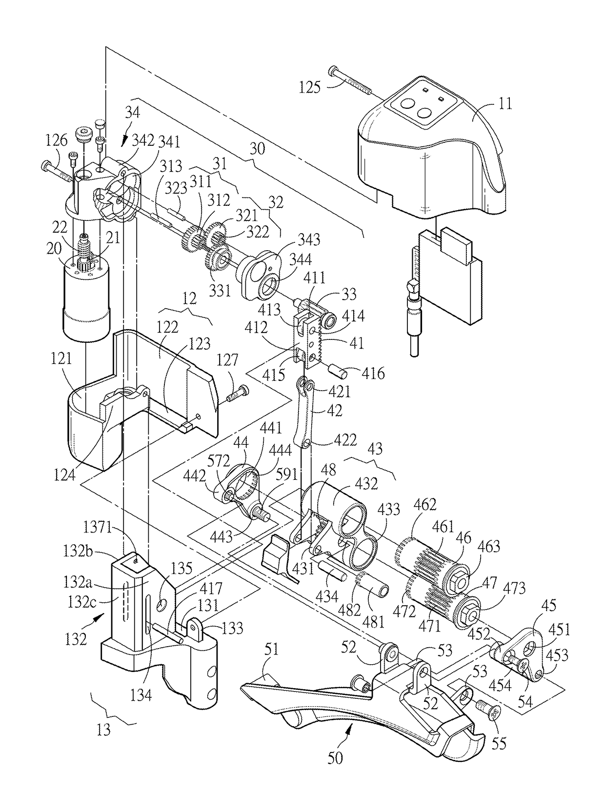
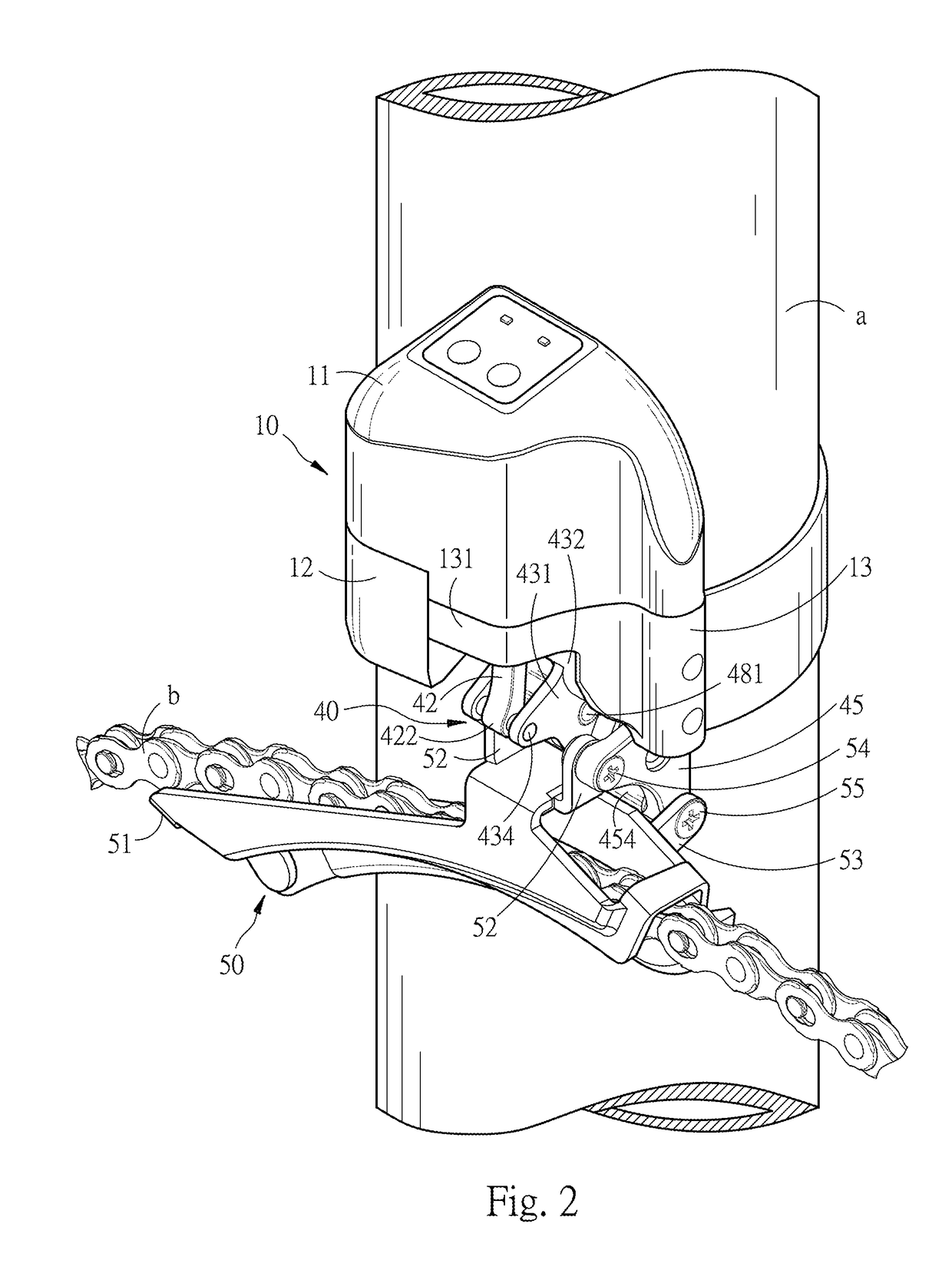
[0028]Referring to FIG. 2 to FIG. 6, an electric front derailleur of the present embodiment comprises a support member 10, a driving unit 20 (an electric motor in the present embodiment), a first transmission unit 30, a second transmission unit 40, and a chain guide 50.

[0029]The support member 10 is mounted on a frame a of a bicycle and comprises an upper cover 11, a shell 12 located below the upper cover 11 and disposed along the shape of the upper cover 11, and a second mounting portion 13.

[0030]The upper cover 11 partially covers a first mounting portion 34. The second mounting portion 13 has a seat plate 131. The seat plate 131 is disposed with a track portion 132 and a lug 133 disposed at a sid...


PUM


Abstract

An electric front derailleur, comprising: a support member, disposed on a frame of a bicycle and having a first mounting portion and a second mounting portion; a driving unit, disposed in the first mounting portion and configured to drive a worm gear to rotate; a first transmission unit, having at least one transmission gear that is driven by the worm gear; a second transmission unit, comprising a rack, a linking member, and a swing member, wherein the rack is engaged with the transmission gear and movably disposed in the second mounting portion, and the linking member has one end pivoted to the rack and the other end pivoted to the swing member; a chain guide, comprising a pivot portion, and a chain guiding portion, wherein the pivot portion are pivoted to the swing member, and the chain guiding portion is configured to move a chain.

Description

BACKGROUND OF THE INVENTIONTechnical Field[0001]The present disclosure involves a front derailleur of a bicycle, and more particularly an electric front derailleur that can prevent a stuck or inaccurate shift of derailleur from occurring when a chain guide is subject to an impact and a force is being transmitted back to a transmission mechanism, causing deformation and dislocation of the transmission mechanism.Description of the Related Art[0002]A front derailleur of a bicycle is mounted on a frame tube of the bicycle, and during a gear shift operation, a chain of the bicycle is moved to a target sprocket wheel by the front derailleur, so as to achieve the purpose of changing gears, which is a very common configuration of current bicycles. Particularly, electric derailleurs have been gradually replacing traditional derailleurs of which the cables are controlled manually.[0003]For a conventional front derailleur, see U.S. Pat. No. 6,648,782 B2, “Actuating Apparatus for A Bicycle Dera...

Claims


Application Information

Patent Timeline
Patent Type & Authority Applications(United States)
IPC IPC(8): B62M9/132B62M25/08
CPCB62M25/08B62M9/132B62M9/134
Inventor SALA, ALFREDO
Owner TIEN HSIN INDS
Why Eureka
Try Eureka