
Apparatus and method for assessing laxity of a joint

a technology of laxity and apparatus, applied in the field of apparatus and method for evaluating the stability of a joint, can solve the problems of inability to provide such data from conventional measurement devices, and the axis of rotation of the knee changing

Active Publication Date: 2017-11-30
HOSPITAL FOR SPECIAL SURGERY
View PDF1 Cites 2 Cited by
  • Summary
  • Abstract
  • Description
  • Claims
  • Application Information

AI Technical Summary

Benefits of technology

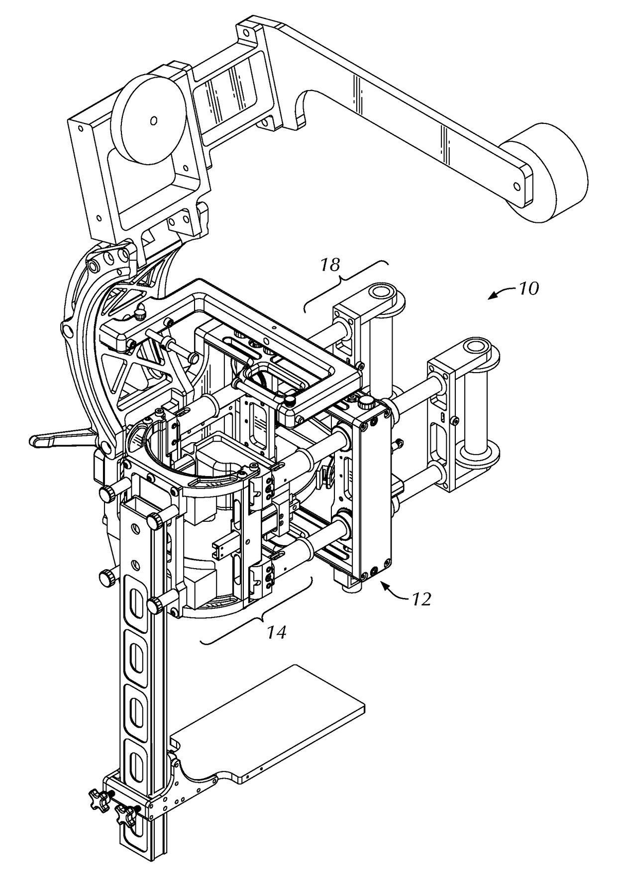
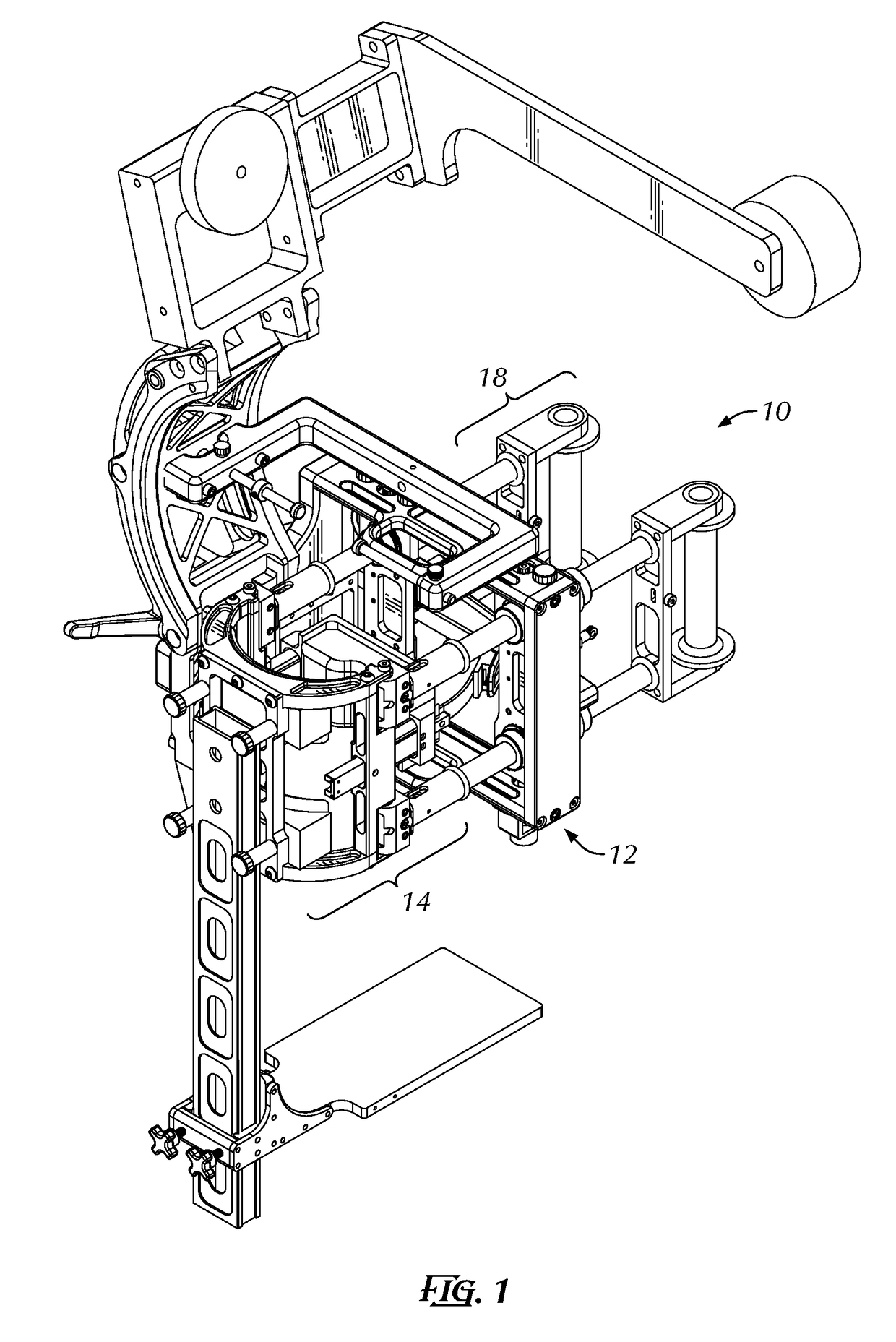
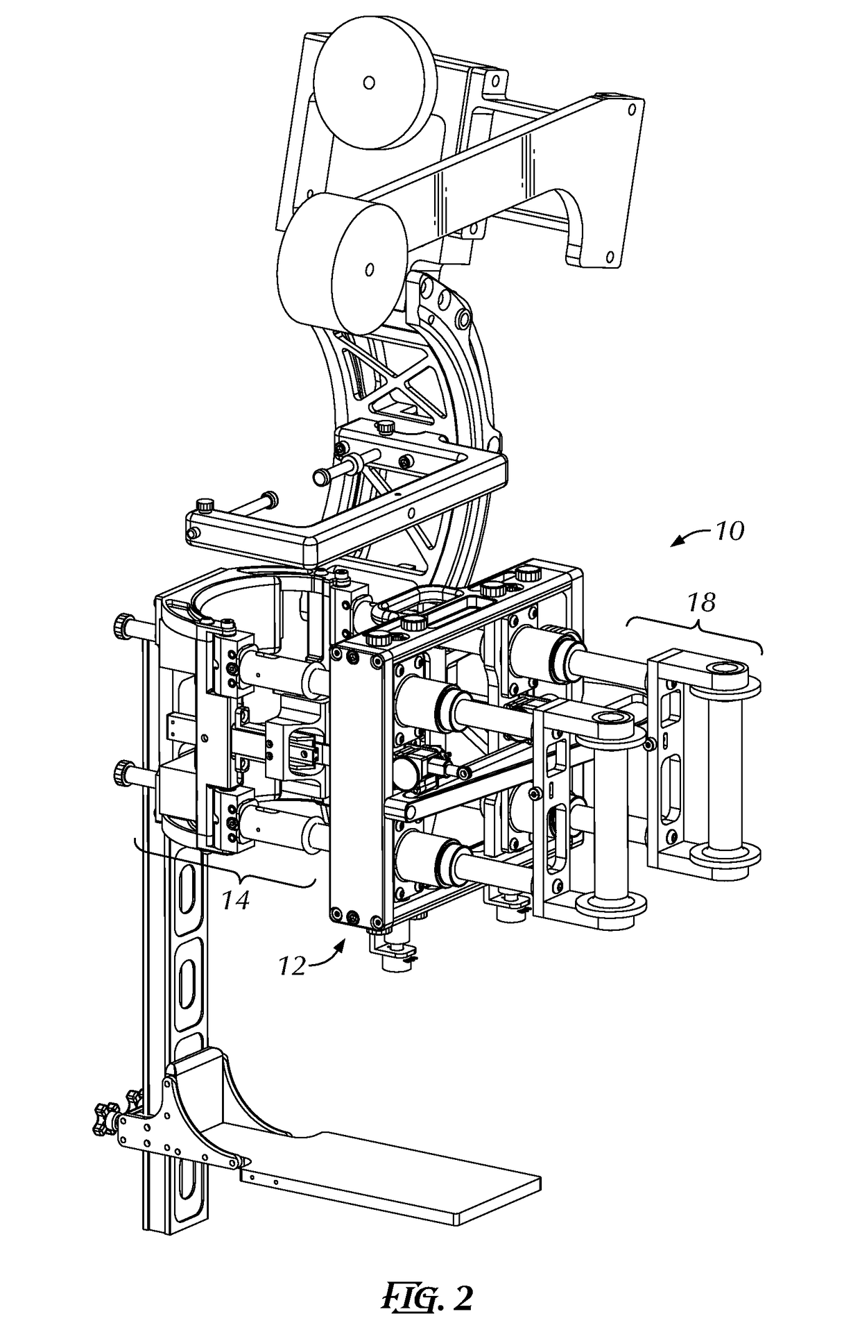
The patent describes a device that allows for the simultaneous or independent application of forces to the knee joint. This device uses a force couple mechanism, which involves a brace that fixes the patient's femur in place while the tibia is fixed to the mechanism. The forces are applied to the tibia through the brace using actuators located on the medial and lateral sides of the knee. The device measures the displacement of the actuators and combines it with information about the fixed distance between them to determine the angle of rotation and the location of the axis of rotation. Overall, this device provides a more accurate and precise means to evaluate the function of the knee joint.

Problems solved by technology

However, the axis of rotation of the knee changes with flexion angle, and is affected by knee injury, ligament reconstructions, or joint replacement.
Conventional measurement devices are unable to provide such data.

Method used


Image

  • Apparatus and method for assessing laxity of a joint
  • Apparatus and method for assessing laxity of a joint
  • Apparatus and method for assessing laxity of a joint

Examples


Embodiment Construction

[0026]Reference will now be made in detail to the exemplary embodiments of the disclosure illustrated in the accompanying drawings. Wherever possible, the same or like reference numbers will be used throughout the drawings to refer to the same or like features. It should be noted that the drawings are in simplified form and are not drawn to precise scale. In reference to the disclosure herein, for purposes of convenience and clarity only, directional terms such as top, bottom, above, below and diagonal, are used with respect to the accompanying drawings. Such directional terms used in conjunction with the following description of the drawings should not be construed to limit the scope of the exemplary embodiments in any manner not explicitly set forth.

[0027]Certain terminology is used in the following description for convenience only and is not limiting. The words “right,”“left,”“lower” and “upper” designate directions in the drawings to which reference is made. The words “inwardly”...


PUM


Abstract

An apparatus for evaluating motions of a joint is provided that is designed for determining stability of an anatomical joint. The apparatus includes a support frame, a fixation assembly for securing a first body segment of a joint, and a displacement assembly mounted to the support frame. The fixation assembly includes an axis of rotation movable relative to the support frame. The displacement assembly includes a first frame pivotably mounted to the support frame and rotatably connected to a first end of the fixation assembly, and a second frame pivotably mounted to the support frame and rotatably connected to a second end of the fixation assembly.

Description

CROSS-REFERENCE TO RELATED APPLICATIONS[0001]This application claims the benefit of U.S. Provisional Application No. 62 / 341,791, filed May 26, 2016, the entire disclosure of which is incorporated by reference herein in its entirety.BACKGROUND OF THE INVENTION[0002]The present invention relates generally to an apparatus and method for evaluating the stability of a joint. The apparatus relates to providing quantitative clinical measurements of an anatomical joint in a clinical or experimental environment.[0003]Numerous instruments have been developed to provide quantitative clinical measurements of e.g., knee stability. Quantitative tests of e.g., anterior-posterior stability rely on application of a force at the center of the knee joint, and measurement of translation with respect to a point at the center of the knee. However, clinicians are often interested in the individual anterior-posterior stability of the medial and lateral compartments of the knee to differentiate the effects ...

Claims


Application Information

Patent Timeline
Patent Type & Authority Applications(United States)
IPC IPC(8): A61B5/00A61B5/103A61B17/68
CPCA61B5/6831A61B5/6835A61B5/6828A61B2017/681A61B5/4528A61B5/103A61B5/4585
Inventor IMHAUSER, CARL
Owner HOSPITAL FOR SPECIAL SURGERY
Learn More