Method for controlling a web in a printing apparatus

Active Publication Date: 2017-11-30
OCE HLDG BV
View PDF4 Cites 2 Cited by
  • Summary
  • Abstract
  • Description
  • Claims
  • Application Information

AI Technical Summary

Benefits of technology

[0067]No persistent deformation of the print area of the web occurs in the ready-to-print mode of the printing system, such as pressure markings of the web in response to a pressure provided by a transport pinch over a longer period or a heating deformation of the web induced by a heating applied by a pre-heat unit to the web. In this way, a deformation of the printed image on the web is prevented, as no persistent deformation of the print area of the web occurs in the ready-to-print mode, which persists during the subsequent printing step. As such, the image material applied in the printing step after the ready-to-print mode cannot fix a deformation of the web as substantially no deformation occurs or the deformation has been so limited that the web is able to recover from the deformation before it is printed on.
[0068]The ready-to-print step e) may comprise the step I) of jogging the print area of the web back and forth such that the web is maintained substantially stationary in the transport direction along the transport path. The jogging of the print area of the web is a repetitive movement of the web back and forth, while the web is kept substantially at the same position along the transport path. In this way, a leading edge and/or a print area of the web may be held close to the printing unit during the ready-to-print step e). The jogging step of the web may comprise a movement in a forth direction, i.e. in the transport direction, over a first jog distance and a movement in a back direction over a second jog direction, wherein the first jog distance and the second jo

Problems solved by technology

When such web deformation zones are upstream of the printing unit, there is a substantial risk t

Method used


Image

  • Method for controlling a web in a printing apparatus
  • Method for controlling a web in a printing apparatus
  • Method for controlling a web in a printing apparatus

Examples


Example

DETAILED DESCRIPTION OF THE DRAWINGS

[0083]The present invention will now be described with reference to the accompanying drawings, wherein the same reference numerals have been used to identify the same or similar elements throughout the several views.

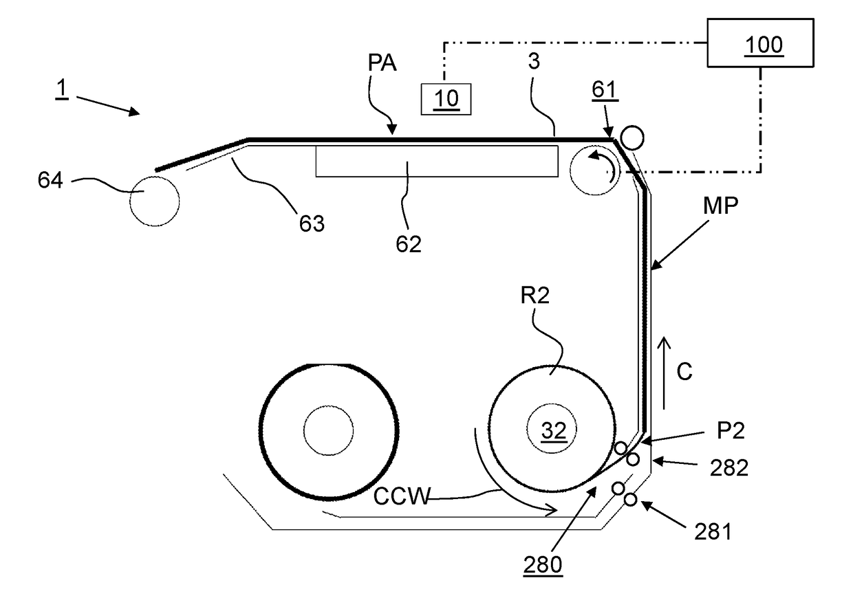
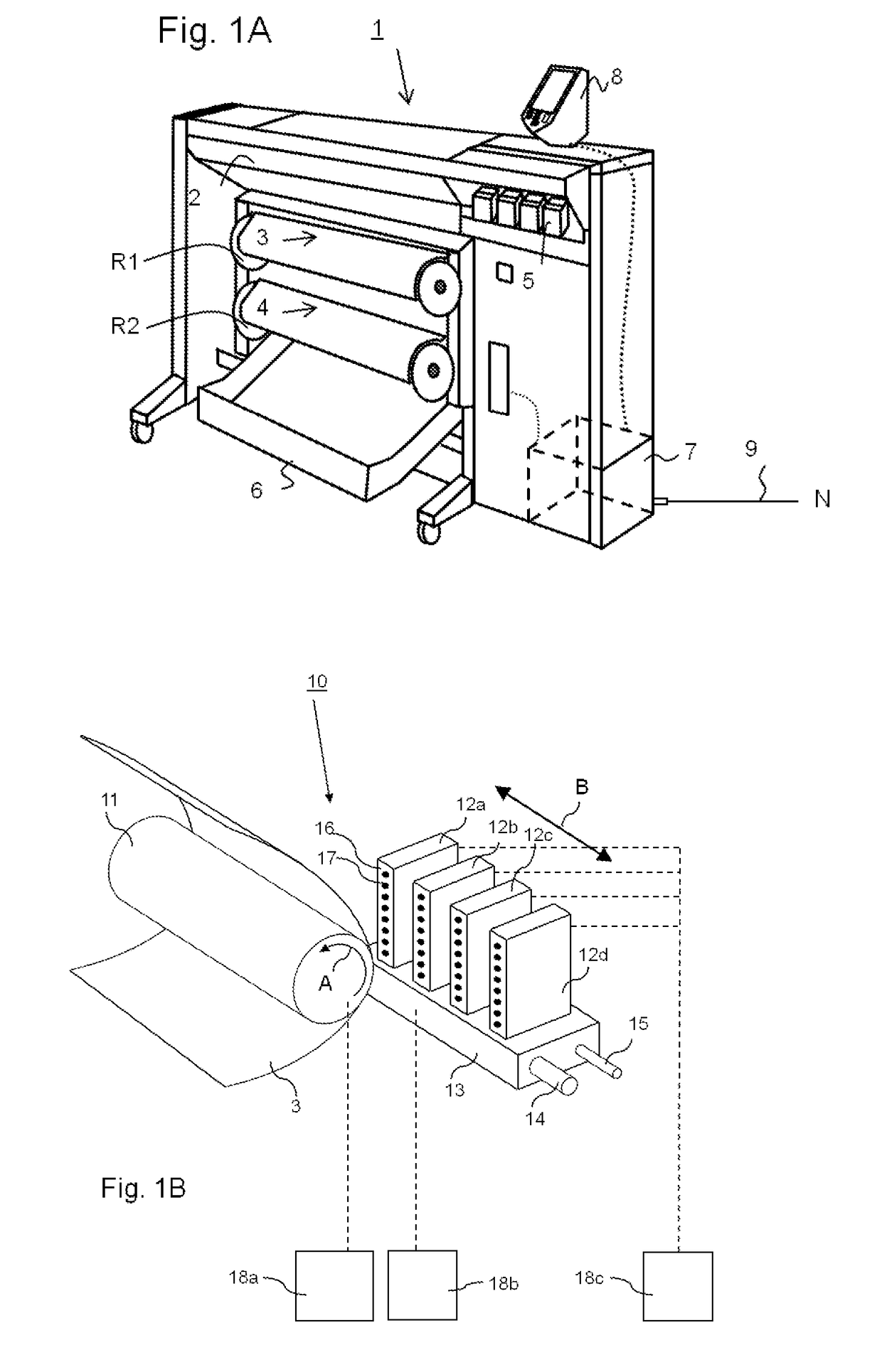
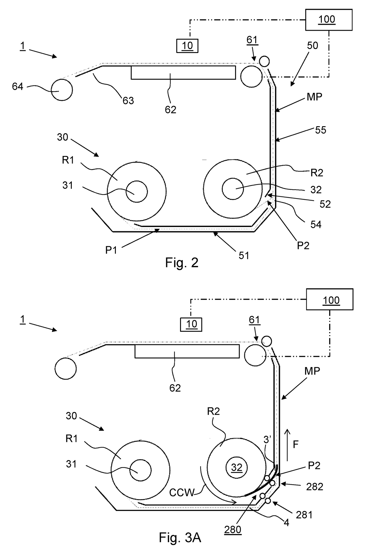
[0084]FIG. 1A shows an image forming apparatus 1, wherein printing is achieved using a wide format inkjet printer. The wide-format image forming apparatus 1 comprises a housing 2, wherein the printing assembly, for example the ink jet printing assembly shown in FIG. 1B is placed. The image forming apparatus 1 also comprises a storage means for storing image receiving member 3, 4, a delivery station to collect the image receiving member 3, 4 after printing and storage means 5 for marking material. In FIG. 1A, the delivery station is embodied as a delivery tray 6. Optionally, the delivery station may comprise processing means for processing the image receiving member 3, 4 after printing, e.g. a folder or a puncher. The wide-format image ...


PUM


Abstract

A method is provided for controlling a web in a printing apparatus The printing apparatus includes a transport assembly for moving the web through a transport path along a printing unit for printing an image onto a print area of the web. The method includes feeding the web from a supply roll through the transport path to the transport assembly; and switching the printing apparatus to a ready-to-print mode, wherein the printing unit does not print an image on the web and the web is maintained ready to be printed on. In a printing mode after the ready-to print mode, the following steps are performed: moving the web through the transport path in a transport direction along the printing unit by the transport assembly; and printing the image onto the print area of the web by the printing unit. The image is printed by applying an image material, which solidifies on the web during the printing step. The ready-to-print mode includes the step of: operating the transport assembly to prevent a deformation of the print area of the web in the transport path, while maintaining the web in the ready-to-print mode. The web is maintained ready to print while preventing a deformation of the print area of the web in the transport path.

Description

FIELD OF THE INVENTION[0001]The present invention pertains to a method and a printing apparatus for controlling a web in a printing apparatus.BACKGROUND ART[0002]In a known web printing system, an ink is printed on a web media to form an image on a print area of the web. The printing system comprises a supply roller for supplying the web from a roll to a transport pinch, which is configured for moving the web through a transport path in a transport direction along a print unit for printing the ink onto the web to form the image. During printing of the ink onto the web, the ink will solidify on the web.[0003]In a known printing method a leading edge of the web is first fed from the supply roll towards the transport pinch. The transport pinch engages the web to drive the web along the transport path. The transport pinch is arranged near the print unit along the transport path for accurately controlling the web, when it moves along the print unit. In case the printing system is not pri...

Claims


Application Information

Patent Timeline
IPC IPC(8): B41F23/04B65H23/32B65H23/188B65H23/192B41J15/16B41F13/02
CPCB41F23/045B65H23/1888B41J15/16B41F13/02B65H23/192B65H2403/50B65H23/32B41J11/0005B41J11/42B41J15/165B41J11/00244B41J11/00214B65H23/1882B65H2403/942B65H20/02B65H2404/1441B65H2404/1452B65H2404/143B65H2404/63B65H2404/61B65H2801/36B65H2601/254B65H2601/272
Inventor HOLTMAN, LODEWIJK T.LEMMENS, MAURICE J.C.COENEN, JEROEN J.G.
Owner OCE HLDG BV
Why Eureka
Try Eureka