Delay measurement circuit and measuring method thereof

a technology of delay measurement and measurement method, which is applied in the direction of electronic circuit testing, measurement devices, instruments, etc., can solve the problems of limited measurement resolution, difficult analysis, and difficulty in calibration of the measurement method of time to voltage converter, and achieve high resolution

Active Publication Date: 2017-11-30
NAT CENT UNIV
View PDF11 Cites 4 Cited by
  • Summary
  • Abstract
  • Description
  • Claims
  • Application Information

AI Technical Summary

Benefits of technology

[0005]The invention is directed to a delay measurement circuit and a measuring method thereof, which are capable of providing a high resolution in case that a circuit with a low area is used.
[0018]According to the above description, in the invention, two delay measurement devices are adopted to measure the transporting delays of a plurality of transporting loops, and an arithmetic operation is performed to the obtained transporting delays to counteract an error probably caused by a manufacturing process variation, so as to improve measurement accuracy. Moreover, by using the delay measurement devices of different structures, a resolution of delay measurement is improved.

Problems solved by technology

In a delay measuring operation of the ring oscillator, a measuring resolution thereof is limited by a structure of the ring oscillator.
Moreover, the measuring method of the time to voltage converter is uneasy to implement calibration and is liable to be influenced by a manufacturing process variation.
Besides that the structure of the ring oscillator may influence a measuring resolution, the vector (logic 0 transited to logic 1, or logic 1 transited to logic 0) that causes an error of the measured delay cannot be confirmed, which causes difficulty in analysis.

Method used


Image

  • Delay measurement circuit and measuring method thereof
  • Delay measurement circuit and measuring method thereof
  • Delay measurement circuit and measuring method thereof

Examples


Embodiment Construction

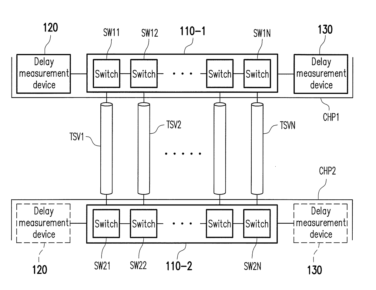
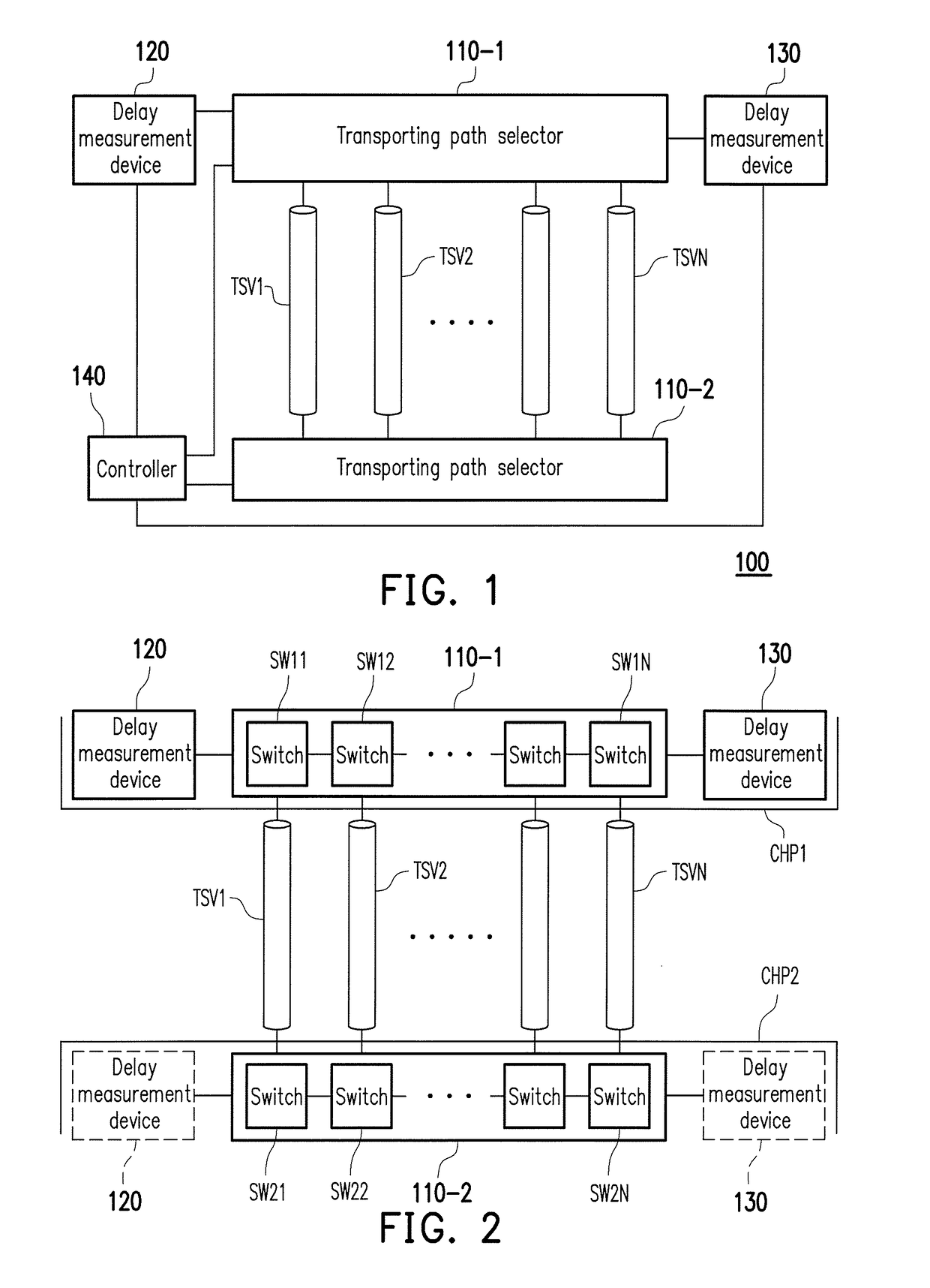
[0027]Referring to FIG. 1, FIG. 1 is a schematic diagram of a delay measurement circuit according to an embodiment of the invention. The delay measurement circuit 100 includes transporting path selectors 110-1 and 110-2, delay measurement devices 120 and 130 and a controller 140. The transporting path selectors 110-1 and 110-2 are coupled to transporting conductive wires TSV1-TSVN, where the transporting path selector 110-1 is coupled to first ends of the transporting conductive wires TSV1-TSVN, and the transporting path selector 110-2 is coupled to second ends of the transporting conductive wires TSV1-TSVN. The delay measurement device 120 is coupled to one of the transporting path selectors 110-1 and 110-2, and the delay measurement device 130 is coupled to one of the transporting path selectors 110-1 and 110-2. Moreover, in FIG. 1, the delay measurement device 120 is coupled to an end of the transporting path selector 110-1 close to the transporting conductive wire TSV1, and the ...


PUM


Abstract

A delay measurement circuit includes a transporting path selector, first and second delay measurement devices, and a controller. The delay measurement circuit forms a plurality of transporting loops through two of a first reference transporting conductive wire, a second reference transporting conductive wire, and a tested transporting conductive wire according to a control signal. The first delay measurement device respectively measures part of the transporting loops to obtain a plurality first transporting delays. The second delay measurement device respectively measures part of the transporting loops to obtain a plurality second transporting delays. The controller generates the control signal, and obtains a transporting delay of the tested transporting conductive wire according to the first transporting delays and the second transporting delays.

Description

CROSS-REFERENCE TO RELATED APPLICATION[0001]This application claims the priority benefit of Taiwan application serial no. 105116063, filed on May 24, 2016. The entirety of the above-mentioned patent application is hereby incorporated by reference herein and made a part of this specification.BACKGROUND OF THE INVENTIONField of the Invention[0002]The invention relates to a delay measurement circuit and a measuring method thereof, and particularly relates to a delay measurement circuit used for measuring transporting conductive wires between chips and a measuring method thereof.Description of Related Art[0003]In conventional technical field, delay measurement circuits are roughly divided into three types including vernier delay line, ring oscillator and time to voltage converter. Although the measuring method of the vernier delay line may provide a better resolution, when delay measurement of a larger range is performed, a required circuit area is greatly increased. In a delay measurin...

Claims


Application Information

Patent Timeline
Patent Type & Authority Applications(United States)
IPC IPC(8): G01R31/28
CPCG01R31/2882G01R31/31725G01R31/31937
Inventor LI, JIN-FUWU, HAN-YUCHOU, CHE-WEICHEN, YONG-XIAO
Owner NAT CENT UNIV
Why Eureka
Try Eureka