Validation tool for an aircraft engine monitoring system

a technology for aircraft engines and validation tools, applied in the direction of testing/monitoring control systems, instruments, stochastic cad, etc., can solve the problems of complicated analysis of data output from different engine monitoring systems, large number of collected data, and long calculation tim

Active Publication Date: 2017-12-07
SN DETUDE & DE CONSTR DE MOTEURS DAVIATION S N E C M A
View PDF0 Cites 7 Cited by
  • Summary
  • Abstract
  • Description
  • Claims
  • Application Information

AI Technical Summary

Benefits of technology

[0027]estimate a minimum quantity of observation data from said probabilistic reliability law, starting from which the value of the quality indicator reaches a predetermined reliability criterion with a probability exceeding a predetermined value, said minimum quantity of observation data corresponding to said volume of observation data that will be used to evaluate the validation of said monitoring equipment.

Problems solved by technology

A lot of resources and time then have to be set aside to perform these tests, and furthermore, the large number of collected data can require a long calculation time.
This can make it more complicated to analyse data output from different engine monitoring systems.

Method used


Image

  • Validation tool for an aircraft engine monitoring system
  • Validation tool for an aircraft engine monitoring system
  • Validation tool for an aircraft engine monitoring system

Examples


first embodiment

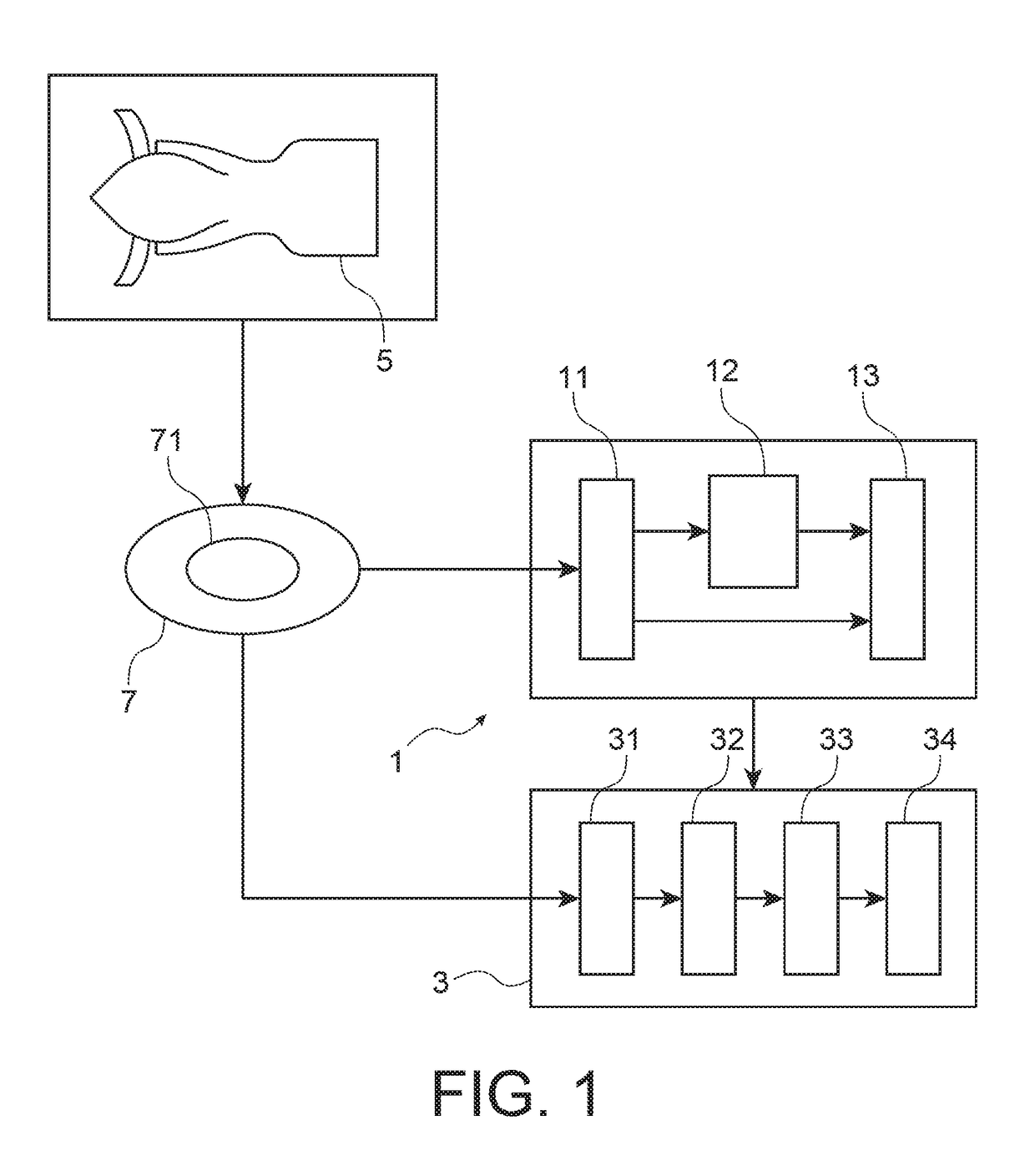
[0088]This first embodiment relates to validation of a generic monitoring system 3 on a test bench 43 before its installation on an aircraft.

[0089]The specification for the monitoring system 3 is broken down into requirement specifications, themselves expressing requirements and objectives. A response is given to a requirement or an objective when there is a test available to validate the expected performances. This test is applicable to at least part of a set of quality indicators KPI that is compared with thresholds defined by specifications. KPI values are calculated by validation scenarios adapted to problems raised by the requirement or the objective. The scenarios are based on observation data providing reasonable coverage of the need.

[0090]Thus, processing means 11 collect observation data 7 for the equipment to be monitored and created on the test bench 43. As a variant, the observation data 7 are collected on aircraft testing the monitoring system 3.

[0091]As already describ...

second embodiment

[0094]This second embodiment relates to the validation and adjustment of said monitoring system 3 after its installation on a series engine 5 of an aircraft 45 by applying at least part of the set of quality indicators on the minimum quantity of observation data collected in flight.

[0095]The monitoring system 3 is already precalibrated on a set of observation measurements made on a test bench 41 according to the first embodiment or on aircraft belonging to airlines who agree to contribute to the development of monitoring systems.

[0096]It will be noted that the aircraft 43 on which the monitoring system 3 is installed will follow its own missions, and maintenance operations specific to the owner airline will also be carried out on it. Thus, validation takes account of the specific use of the engine on which it is installed.

[0097]As described above, the processing means 12 collect observation data 7 for the equipment to be monitored produced on the engine during operation. The analysi...


PUM


Abstract

A tool for validation of a system for monitoring at least one piece of equipment in an aircraft engine, also comprising a computer configured to: collect observation data related to the equipment, calculate a current value of at least one quality indicator on a current quantity of observation data, estimate the probability that the current value of the quality indicator reaches a predetermined reliability criterion, thus forming a probabilistic reliability law, and estimate a minimum quantity of observation data from the probabilistic reliability law, starting from which the value of the quality indicator reaches a predetermined reliability criterion with a probability exceeding a predetermined value.

Description

TECHNICAL DOMAIN[0001]This invention relates to the domain of aircraft engine monitoring systems and most particularly, a tool for validation of a system for monitoring equipment of the aircraft engine.STATE OF PRIOR ART[0002]Monitoring systems are used to check that the various equipment of the aircraft engine is functioning correctly. For example, there is one monitoring system to analyse the behaviour of the engine during the ignition process, another system to analyse the gas trajectory, yet another system to detect clogging of filters, and another system to analyse oil consumption, etc.[0003]All these monitoring systems combined are sufficient to improve the safety and reliability of aircraft engines. In particular, they make it possible to avoid or limit in-flight shutdowns, reduce delays or cancellations of flights, and more particularly facilitate engine maintenance by anticipating failures and identifying faulty or defective components.[0004]At the present time, there is a ...

Claims


Application Information

Patent Timeline
Patent Type & Authority Applications(United States)
IPC IPC(8): G07C5/08F01D17/02F01D21/00B64F5/60B64D45/00G06F30/15G06F111/08
CPCG07C5/0816B64F5/60B64D45/00F01D17/02F01D21/003G05B23/024G01M15/14G05B23/02G06F30/00
Inventor LACAILLE, JEROME HENRI, NOEL
Owner SN DETUDE & DE CONSTR DE MOTEURS DAVIATION S N E C M A
Why Eureka
Try Eureka