Time of flight ranging for flash control in image capture devices

a technology of image capture device and time of flight range, which is applied in the direction of color television details, instruments, television systems, etc., can solve the problems of captured image being “washed out, object being too dark in the captured image, and unnecessary activation of flash devices

Inactive Publication Date: 2017-12-07
STMICROELECTRONICS (RES & DEV) LTD +1
View PDF6 Cites 22 Cited by
  • Summary
  • Abstract
  • Description
  • Claims
  • Application Information

AI Technical Summary

Problems solved by technology

Conversely, the flash device is deactivated when ambient light is high, making activation of the flash device unnecessary.
When the object is close to the image capture device and the flash device activated, the flash illumination of the object can be too strong and result in the captured image being “washed out,” such as where the object is a person's face, for example.
If the object is farther away, the flash illumination of the object may be too weak, resulting in the object being too dark in the captured image.
This can result in the issues noted above.
In addition, where an object is located within a field of view of an image capture device also affects how effective the flash device is in properly illuminating the object being images.
Multiple objects within the field of view can result in similar issues during image capture.
In this situation, the flash device may possibly illuminate some objects too much so they appear washed out in the captured image while other objects are not illuminated enough and thus appear too dark in the captured image.

Method used


Image

  • Time of flight ranging for flash control in image capture devices
  • Time of flight ranging for flash control in image capture devices
  • Time of flight ranging for flash control in image capture devices

Examples


Embodiment Construction

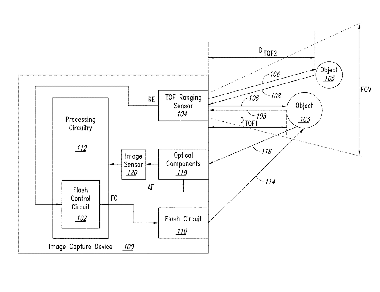
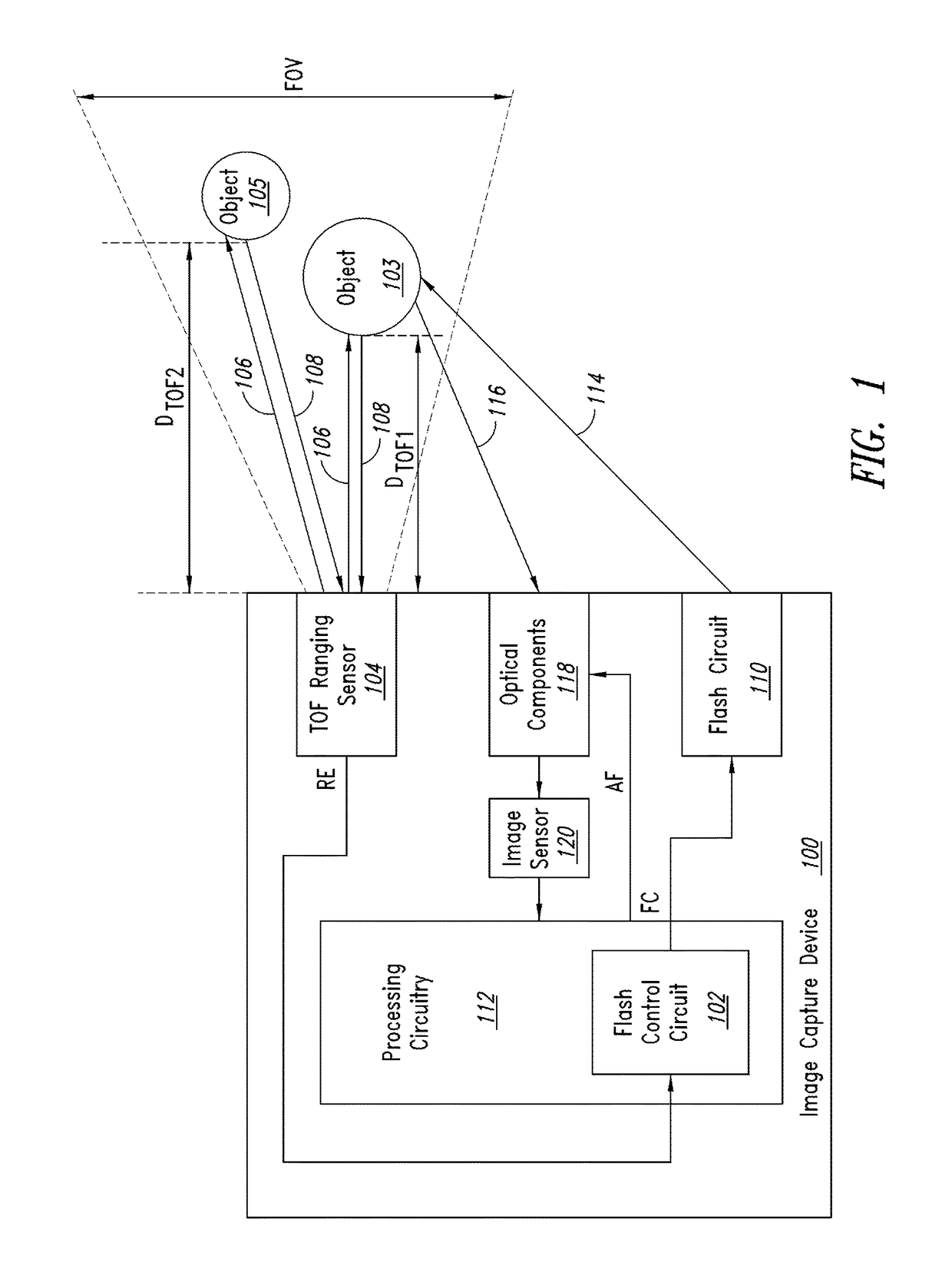
[0016]FIG. 1 is a functional block diagram of an image capture device 100 including flash control circuitry 102 that controls flash illumination of objects 103 and 105 being imaged based upon sensed distances DTOF1 and DTOF2 between each of the objects and the image capture device according to one embodiment of the present disclosure. A time of flight (TOF) ranging sensor 104 transmits an optical pulse signal 106 that is incident upon the objects 103 and 105 within an overall field of view FOV of the TOF ranging sensor. The transmitted optical pulse signal 106 reflects off the objects 103 and 105 and portions of the reflected pulse signals propagate back to the TOF ranging sensor 104 as return optical pulse signals 108. The TOF ranging sensor 104 determines the ranges or distances DTOF1 and DTOF2 between each of the objects 103, 105 and the image capture device 100, and the flash control circuitry 102 thereafter controls flash illumination of these objects based upon these determine...


PUM


Abstract

A flash control circuit of an image capture device includes a time-of-flight ranging sensor configured to sense distances to a plurality of objects within an overall field of view of the time-of-flight ranging sensor. The time-of-flight sensor is configured to generate a range estimation signal including a plurality of sensed distances to the plurality of objects. Flash control circuitry is coupled to the time-of-flight ranging sensor to receive the range estimation signal and is configured to generate a flash control signal to control a power of flash illumination light based upon the plurality of sensed distances. The time-of-flight sensor may also generate a signal amplitude for each of the plurality of sensed objects, with the flash control circuitry generating the flash control signal to the control the power of the flash illumination based on the plurality of sensed distances and signal amplitudes.

Description

BACKGROUNDTechnical Field[0001]The present disclosure relates generally to flash control in image capture devices such as digital cameras, and more specifically to the utilization of time of flight range detection in flash control of image capture devices.Description of the Related Art[0002]In image capture devices, such as digital cameras, control of a flash device is primarily performed based on ambient light. When ambient light is low, the flash device is activated to illuminate an object for capture of an image of the object. Conversely, the flash device is deactivated when ambient light is high, making activation of the flash device unnecessary. The distance of the object being imaged from the image capture device, however, can greatly influence the effectiveness of the flash device and quality of the captured image. When the object is close to the image capture device and the flash device activated, the flash illumination of the object can be too strong and result in the captu...

Claims


Application Information

Patent Timeline
Patent Type & Authority Applications(United States)
IPC IPC(8): H04N5/235G01S17/10G01S17/02H04N5/225G01S7/486G01S7/4863G01S7/4865G01S17/86
CPCH04N5/2354G01S17/10H04N5/2256G01S7/4863G01S17/023G01S7/4816G01S7/4815G01S7/484G01S7/4865H04N23/56H04N23/74G01S17/86
Inventor YANG, XIAOYONGMOORE, JOHN KEVIN
Owner STMICROELECTRONICS (RES & DEV) LTD
Why Eureka
Try Eureka