A 3d-camera device including a dirt detection unit

a technology of 3d camera and detection unit, which is applied in the direction of measurement devices, television systems, instruments, etc., can solve the problems of affecting the quality of images taken by the camera device, affecting the operation accumulating dirt, etc., to achieve the effect of improving the operational reliability of the camera device, short exposure time of the time-of-flight, and high accuracy

Active Publication Date: 2019-12-12
VEONEER SWEDEN AB
View PDF0 Cites 20 Cited by
  • Summary
  • Abstract
  • Description
  • Claims
  • Application Information

AI Technical Summary

Benefits of technology

[0016]A notable advantage is provided by integrating the dirt detection unit in a 3D-camera device with a Time-Of-Flight sensor and utilizing the Time-of-Flight sensor for light detection. Namely, the very short exposure time of the Time-of-Flight sensor makes it possible to exclude, with high accuracy, exposures of light reflected from background objects from light that originates from dirt on the transparent cover of the 3D-camera device. This in turn results in that essentially all error sources emanating from reflected light pulses from object in the surroundings of the camera device may eliminated and that a true value for the amount of dirt on the transparent cover may be obtained.
[0017]According to one alternative of the 3D-camera device the control unit is configured to switch the light source between an off-state in which no light is emitted from the light source and an on-state in which light is emitted from the light source such that light is emitted as a light pulse from the light source, and to control the Time-of-Flight sensor to perform an exposure and to synchronize the exposure of the Time-of-Flight sensor with the light pulse such that the end of the exposure overlaps the beginning of the light pulse. The advantage thereof is that the Time-of-Flight sensor to a very high extent only is exposed to light reflected from dirt on the transparent cover.
[0018]Preferably, the control unit is configured to switch the light source repeatedly between an on-state and an off-state such that a series of light pulses are emitted from the light source and to control the Time-of-Flight sensor to perform a first series of exposures which are synchronized with the series of light pulses from the light source such the end of each exposure overlaps the beginning of a light pulse, and to control the Time-of-Flight sensor to perform a second series of exposures which are synchronized with the series of light pulses from the light source such the each exposure is performed prior to the beginning of a light pulse and to determine the presence of dirt on the outer cover of the transparent cover from the difference between the magnitude of the signal (L) from the first series exposures and from the second series exposures. The advantage thereof is that an essentially completely true reading of the presence of dirt on the transparent cover of the 3D-camera device is achieved. This is so, because the second series of exposures essentially cancels the small portion of light reflected from the background in the first series of exposures.
[0019]The integration of a dirt detection unit directly within the 3D-camera device results in a substantial increase in the operational reliability of the camera device. It also increases the operational reliability of the process that the camera device is set to control. A further advantage of the camera device is that it is compact. Moreover, since the dirt detection unit utilizes several components already present in the 3D camera device it may be produced at relatively low cost.
[0020]In an embodiment of the invention, the camera device includes a housing having a wall portion, wherein the transparent cover is arranged in the wall portion, thereby forming a window in the housing. Thereby, a compact and robust 3D-camera device is achieved in which all components of the 3D-camera device are protected within the housing.

Problems solved by technology

A common problem when using this type of camera devices is that dirt accumulates on the transparent cover on the end of the light guide and impairs the quality of the images taken by the camera device.
Over time, the transparent cover may be soiled to a degree at which the camera device fails to control the process, which then is interrupted.
This type of dirt induced interruptions results in unnecessary and costly service calls which could have been avoided by a simple cleaning operation.
However, the detection system of JP2008068701 is complicated since it involves a distinguishing determination of both dirt and rain.

Method used


Image

  • A 3d-camera device including a dirt detection unit
  • A 3d-camera device including a dirt detection unit
  • A 3d-camera device including a dirt detection unit

Examples


Embodiment Construction

[0032]The 3D-camera device according to the present disclosure will now be described more fully hereinafter. The camera device according to the present disclosure may however be embodied in many different forms and should not be construed as limited to the embodiments set forth herein. Rather, these embodiments are provided by way of example so that this disclosure will be thorough and complete, and will fully convey the scope of the present disclosure to those persons skilled in the art. Same reference numbers refer to same elements throughout the description.

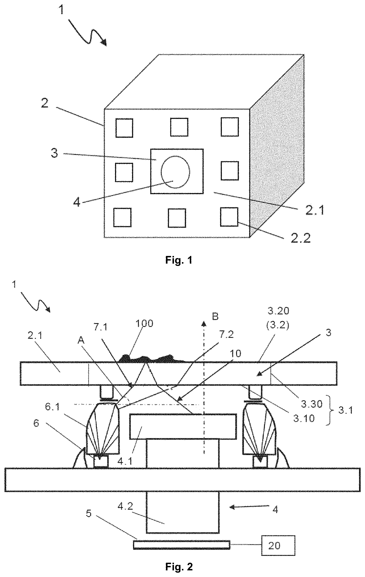
[0033]FIG. 1 shows a schematic drawing of a 3D-camera device 1 according to a first embodiment of the present disclosure.

[0034]The 3D-camera device 1 includes a housing 2 which encloses the components of the 3D-camera device. Typically, the housing 2 is designed such that it forms a wall around a sealed internal space in which the components of the 3D-camera device are arranged. A light transparent cover 3 of a light guide 4 (...


PUM


Abstract

A 3D-camera device (1) comprising a Time-Of-Flight sensor (5) and a light guide (4) with a light transparent cover (3). A light source (6) is arranged to emit light (7) into the transparent cover (3), whereby at least a portion (10) of the emitted light (7) is reflected out through a second portion (3.1) of the transparent cover (3) by dirt (100) present on the outer surface (3.20) of the transparent cover (3). The Time-Of-Flight sensor (5) is arranged to receive light (10) reflected by dirt (100) on the outer surface (3.20) of the transparent cover (3) and to output a signal (L) relative the amount of received reflected light (10). A control unit (20) configured to determine the presence of dirt (100) on the outer surface (3.20) of the transparent cover (3) from the magnitude of the signal (L) from the Time-Of-Flight sensor (5).

Description

CROSS-REFERENCE TO RELATED APPLICATIONS[0001]This application is a 35 U.S.C. § 371 national phase of PCT International Application No. PCT / EP2018 / 054413, filed Feb. 22, 2018, which claims the benefit of priority under 35 U.S.C. § 119 to European Patent Application No. 17158100.2, filed Feb. 27, 2017, the contents of which are incorporated herein by reference in their entirety.TECHNICAL FIELD[0002]The present disclosure relates to a 3D-camera device with a Time-of-Flight sensor and a light guide, such as a camera lens, having a first end for receiving incident light with a light transparent cover and a dirt detection unit for detecting dirt on the outer surface of the transparent cover.BACKGROUND[0003]Camera devices, such as 2D- or 3D-digital camera devices, may be employed to control or monitor processes in dirty environments such as industrial manufacturing processes, or in milking robots in the agriculture for instance.[0004]To withstand operation in dirty environments, the camera...

Claims


Application Information

Patent Timeline
Patent Type & Authority Applications(United States)
IPC IPC(8): G01S7/497H04N13/254H04N13/296H04N17/00G08B21/18
CPCG01S7/497G01S2007/4975H04N13/296G08B21/182H04N17/002H04N13/254G02B27/0006G01S17/894G01S7/4815H04N23/811H04N23/50
Inventor ASTROM, RICKARDERIKSSON, EVELINAWIHLBECK, JONASEMIL, HALLSTIG
Owner VEONEER SWEDEN AB
Why Eureka
Try Eureka