Method and system to reduce stray light reflection error in time-of-flight sensor arrays

a sensor array and time-of-flight technology, applied in the field of differential pixel sensor arrays, can solve the problems of stray light reflection error in time-of-flight sensor arrays, reduce the effect of reflection, and reduce the mal-effect of stray radiation

Active Publication Date: 2012-06-05
MICROSOFT TECH LICENSING LLC
View PDF4 Cites 20 Cited by
  • Summary
  • Abstract
  • Description
  • Claims
  • Application Information

AI Technical Summary

Benefits of technology

[0019]Mechanically, magnitude of the stray light reflections preferably is reduced by reducing surface reflectivity within the IC containing the sensor array. Reflectivity is reduced in some embodiments by coating the uppermost surface of the array structure with black ink or the like, leaving of course unpainted window areas overlying the light sensitive regions of the array. The unpainted window areas preferably are somewhat oversized relative to the underlying light sensitive regions because incoming optical energy may arrive at an angle relative to the plane of the array. Such inking or painting can help reduce stray light reflections and undesired haze.
[0020]Other embodiments further reduce the undesired effects of stray light reflections using a software modeling approach that can be used with or instead of the above-noted mechanical approach. After fabrication, the pixel array is subjected to a spatial impulse of optical energy that is directed toward one region of the array. Because stray light reflections will occur, even with an inked windowed upper array surface, more than one pixel will output a detection signal responsive to the input impulse. The brightness or haze signal produced at the non-targeted pixels is measured and an average haze brightness value is determined. In this embodiment, as a corrective measure during actual run time operation of the TOF system and array, an average correction signal based upon the input impulse test is applied to the detection output preferably from each pixel in the array. This simple model has been found to reduce stray light reflections.
[0023]Other embodiments further reduce mal-effects of stray radiation by coating otherwise reflective regions of the pixel sensor array with a non-reflective surface, leaving openings or windows for regions intended to pass incoming optical energy to the underlying pixel detectors.
[0024]Still other embodiments reducing the effect of reflections in the lens and other elements in the optical path of the TOF system. This preferably includes coating the lens and other transmissive elements with anti reflective coating, and / or by designing the optical path in such that stray reflections do not fall upon the sensor array.

Problems solved by technology

The undesired result is that incoming optical energy that ideally would be sensed by a single pixel is instead reflected internally and is sensed by many pixels.
But in high performance TOF systems, such parasitic stray light and resultant haze can contribute to substantial measurement error in that wrong values of range Z will result from errors in detected phase-shift.

Method used


Image

  • Method and system to reduce stray light reflection error in time-of-flight sensor arrays
  • Method and system to reduce stray light reflection error in time-of-flight sensor arrays
  • Method and system to reduce stray light reflection error in time-of-flight sensor arrays

Examples


Embodiment Construction

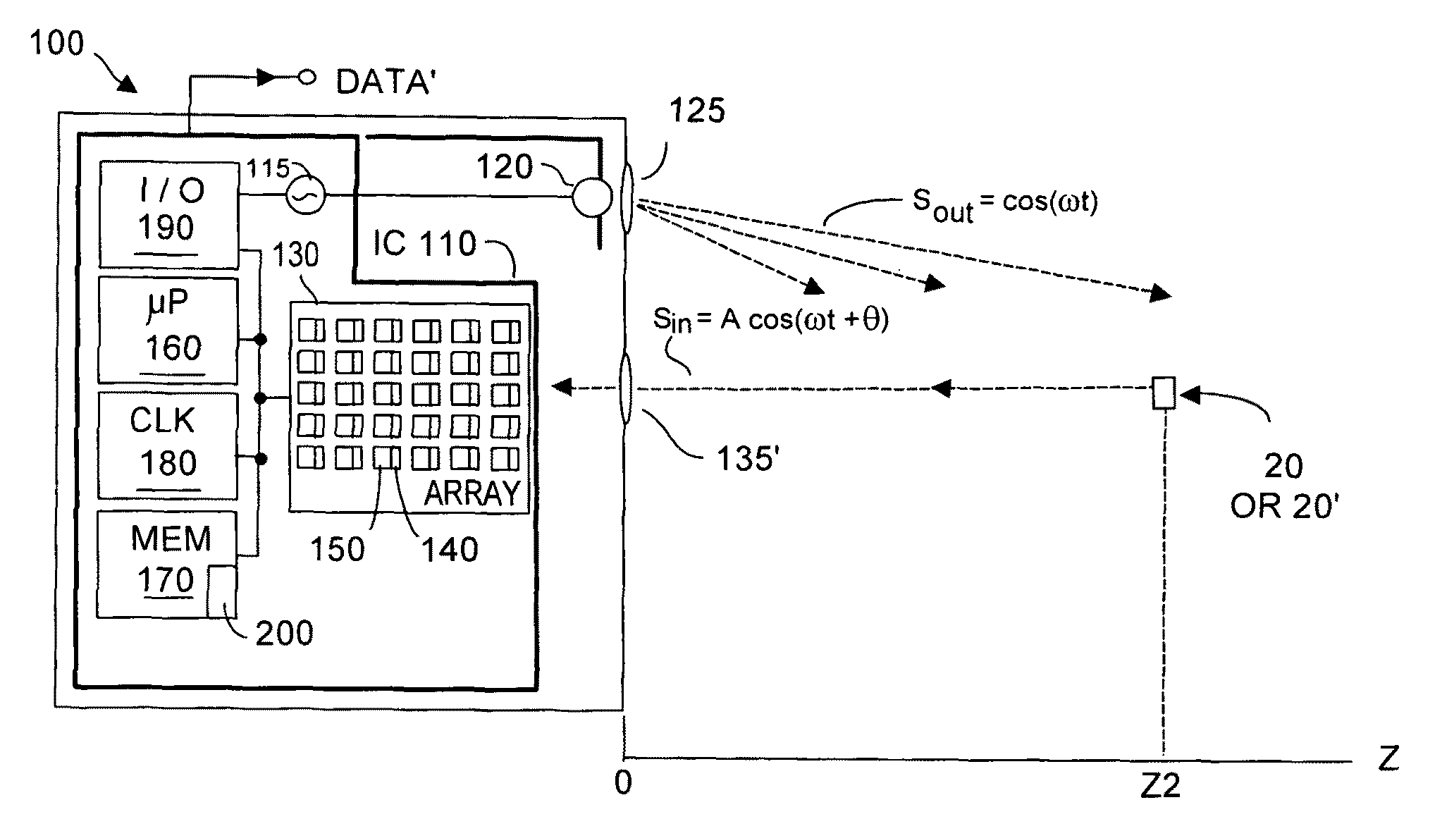
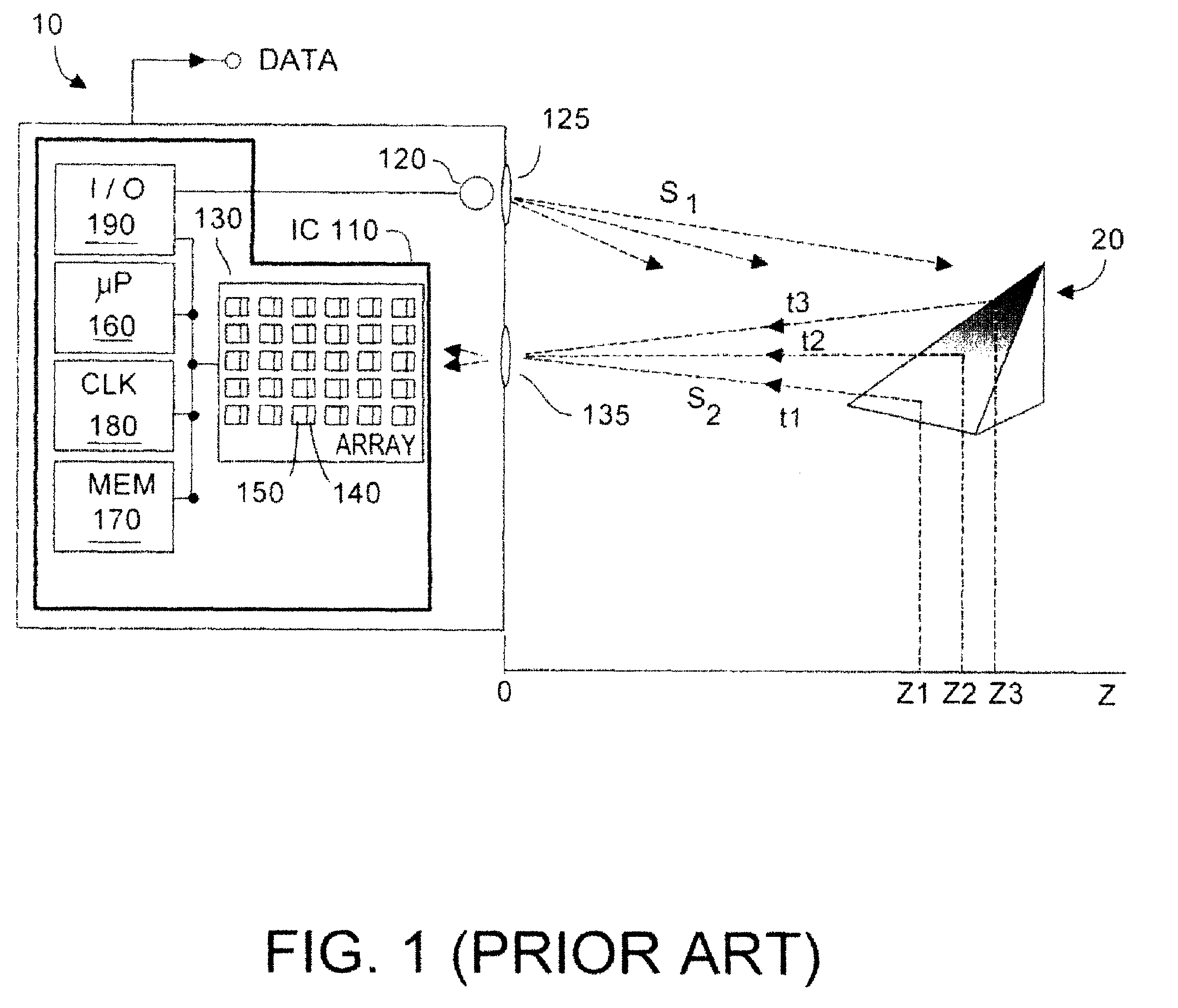
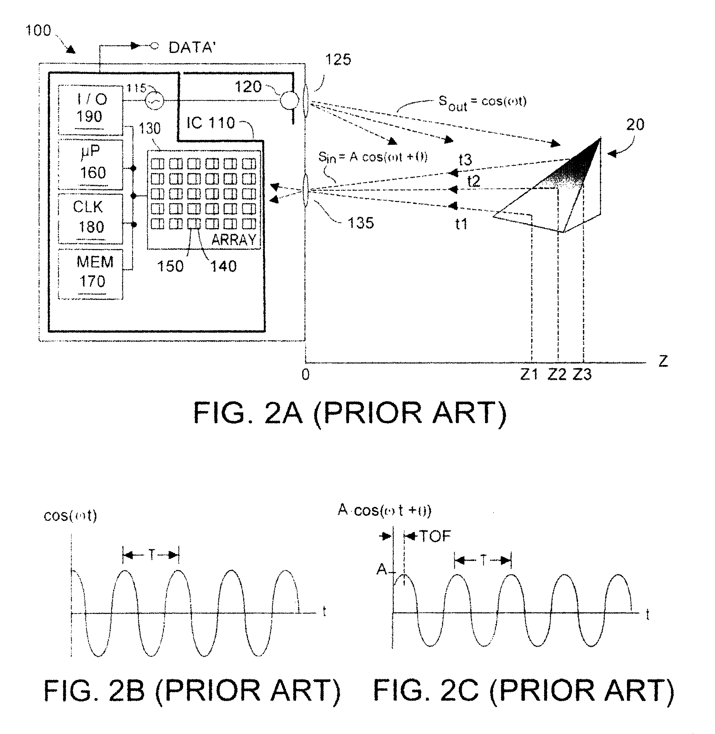
[0037]Referring to FIG. 3A, in a perfect time-of-flight (TOF) system 100, there would be a one-to-one relationship between points on the imaged surface of target object 20 and detector pixels 140 within array 130. But in a practical TOF system, some portion of the optical energy, or light, received at a given pixel within array 130 is actually light intended for another pixel. This amount of misdirected light (termed stray light herein) is usually small and is not a cause for concern. However in high performance TOF systems this parasitic stray light can lead to substantial measurement errors. Although descriptions herein will primarily be given with respect to phase-type differential TOF systems, it is to be understood that haze-type correction can be made to non-phase type TOF systems, according to embodiments of the present invention.

[0038]Stray light can be due to a number of sources and can have a number of characteristics. Stray light may arise from focus error, and / or haze or...


PUM


Abstract

Haze-type phase shift error due to stray light reflections in a phase-type TOF system is reduced by providing a windowed opaque coating on the sensor array surface, the windows permitting optical energy to reach light sensitive regions of the pixels, and by reducing optical path stray reflection. Further haze-type error reduction is obtained by acquiring values for a plurality (but not necessarily all) of pixel sensors in the TOF system pixel sensor array. Next, a correction term for the value (differential or other) acquired for each pixel in the plurality of pixel sensors is computed and stored. Modeling response may be made dependent upon pixel (row, column) location within the sensor array. During actual TOF system runtime operation, detection data for each pixel, or pixel groups (super pixels) is corrected using the stored data. Good optical system design accounts for correction, enabling a simple correction model.

Description

RELATIONSHIP TO PENDING APPLICATIONS[0001]Priority is claimed to co-pending U.S. provisional patent application Ser. No. 61 / 124,104 filed 11 Apr. 2008, entitled Method and System to Reduce Stray Light Reflection Error in Time-of-Flight Sensor Arrays, and also to co-pending U.S. provisional patent application Ser. No. 61 / 203,599 filed 26 Dec. 2008 entitled Improvements to Time-of-Flight Sensing. Each of the provisional patent applications is assigned to Canesta, Inc., assignee herein.FIELD OF THE INVENTION[0002]The present invention relates generally to differential pixel sensor arrays used in time-of-flight (TOF) sensor arrays, and more particularly to reducing the effects of stray light reflection error in TOF systems using such sensor arrays.BACKGROUND OF THE INVENTION[0003]In many applications it is desired to know the Z-distance to a target object. A relatively accurate class of range or Z distance systems are the so-called time-of-flight (TOF) systems, many of which have been p...

Claims


Application Information

Patent Timeline
Patent Type & Authority Patents(United States)
IPC IPC(8): G01C3/08
CPCG01S7/497G01S17/36G01S17/89G01S17/894
Inventor BAMJI, CYRUS
Owner MICROSOFT TECH LICENSING LLC
Why Eureka
Try Eureka