
Time of flight sensor, camera using time of flight sensor, and related method of operation

a technology of time of flight and time of flight, applied in the field of time of flight (tof) sensors, can solve the problems of difficult to produce high resolution information for motion or other phenomena, limited, conventional tof sensors, etc., and achieve the effect of improving sensing and increasing the resolution of the sensor

Inactive Publication Date: 2013-09-12
SAMSUNG ELECTRONICS CO LTD
View PDF24 Cites 20 Cited by
  • Summary
  • Abstract
  • Description
  • Claims
  • Application Information

AI Technical Summary

Benefits of technology

The patent describes a technology that improves the resolution of a ToF sensor or ToF camera by detecting movement and controlling the view angle of the sensor to increase the number of pixels that sense the movement. This can lead to better sensing performance and improve the accuracy of the sensor.

Problems solved by technology

Although many ToF sensors can obtain relatively accurate distance information, they are somewhat limited due to low resolution.
For example, unlike digital cameras, ToF sensors are not generally designed with large arrays of pixel sensors.
Consequently, it can be difficult for conventional ToF sensors to produce high resolution information regarding motion or other phenomena within its field of sensing.

Method used


Image

  • Time of flight sensor, camera using time of flight sensor, and related method of operation
  • Time of flight sensor, camera using time of flight sensor, and related method of operation
  • Time of flight sensor, camera using time of flight sensor, and related method of operation

Examples


Embodiment Construction

[0023]Embodiments of the inventive concept are described below with reference to the accompanying drawings. These embodiments are presented as teaching examples and should not be construed to limit the scope of the inventive concept.

[0024]The terminology used herein is for the purpose of describing particular embodiments only and is not intended to be limiting of exemplary embodiments of the inventive concept. As used herein, the singular forms “a”, “an” and “the” are intended to include the plural forms as well, unless the context clearly indicates otherwise. The terms “comprises”, “comprising,”, “includes” and / or “including”, when used herein, indicate the presence of stated features, integers, steps, operations, elements, and / or components, but do not preclude the presence or addition of one or more other features, integers, steps, operations, elements, components, and / or groups thereof.

[0025]Although the terms first, second, third etc. may be used herein to describe various feat...


PUM


Abstract

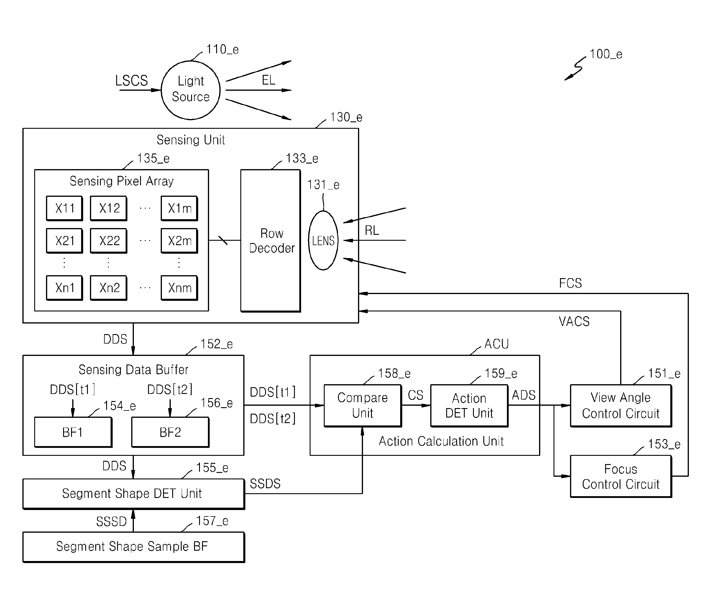
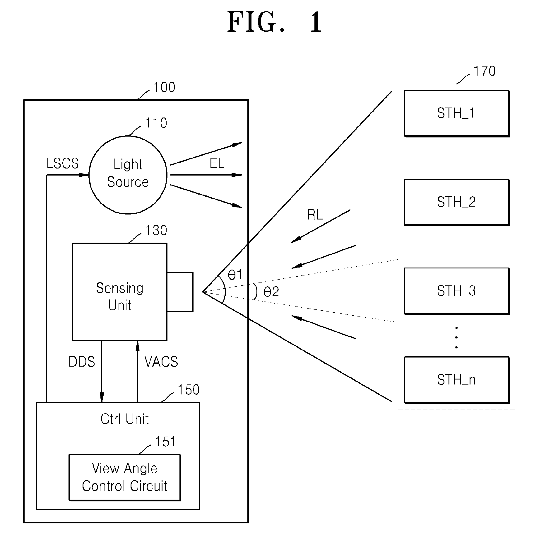
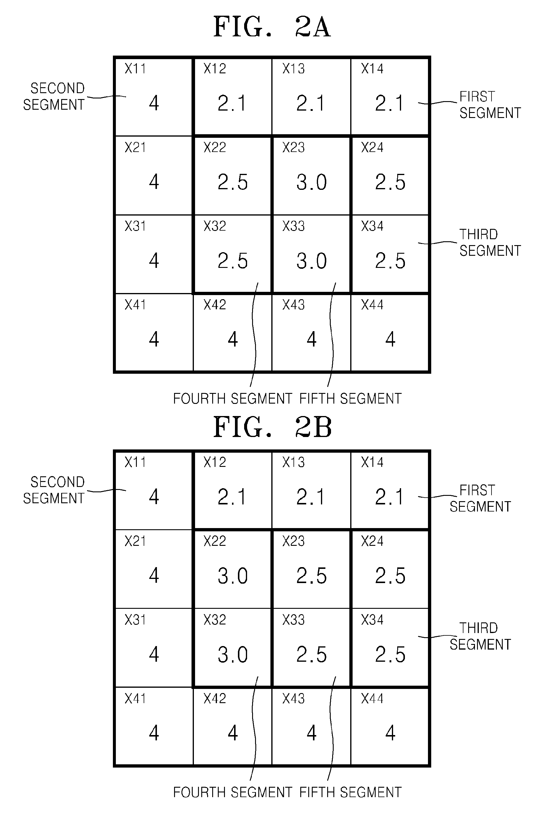
A time of flight (ToF) sensor comprises a light source configured to irradiate light on a subject, a sensing unit comprising a sensing pixel array configured to sense light reflected from the subject and to generate a distance data signal, and a control unit comprising a view angle control circuit. The view angle control circuit is configured to detect movement of the subject based on the distance data signal received from the sensing unit and to control a view angle of the sensing unit to increase a number of sensing pixels in the sensing pixel array that are used to sense a region in which the detected movement occurs.

Description

CROSS-REFERENCE TO RELATED APPLICATIONS[0001]This application claims priority under 35 U.S.C. §119 to Korean Patent Application No. 10-2012-0023600 filed on Mar. 7, 2012, the subject matter of which is hereby incorporated by reference.BACKGROUND OF THE INVENTION[0002]The inventive concept relates generally to time of flight (ToF) sensors. More particularly, certain embodiments of the inventive concept relate to a ToF sensor that can be adjusted in response to activity such as motion within its sensing field.[0003]A ToF sensor is a device that determines the flight time of a signal of interest. For example, an optical ToF sensor may determine the time of flight of an optical signal (e.g., near infrared light at ˜850 nm) by detecting its time of emission from a light source (t_em), detecting its time of reception at a light sensor (t_re), and then subtracting the time of reception from the time of emission according to the following equation ToF=t_re−t_em, referred to as equation (1)....

Claims


Application Information

Patent Timeline
Patent Type & Authority Applications(United States)
IPC IPC(8): G01S17/50
CPCG01S17/50H04N23/62H04N23/67
Inventor KYUNG, KYU-MINKIM, TAE-CHANBAE, KWANG-HYUKLEE, SEUNG-HEE
Owner SAMSUNG ELECTRONICS CO LTD
Learn More