
Method for integrating a backing-structure assembly in a structure of an aircraft or spacecraft

Active Publication Date: 2017-12-14
AIRBUS OPERATIONS GMBH
View PDF3 Cites 3 Cited by
  • Summary
  • Abstract
  • Description
  • Claims
  • Application Information

AI Technical Summary

Benefits of technology

The patent is about improving the way an aircraft or spacecraft's backing-structure is integrated into the overall structure. The goal is to make the process simpler but still reliable, allowing for tolerance compensation that is more easily achieved.

Problems solved by technology

When connecting a relatively large number of individual components in the course of integrating complex assemblies, it has proven to be relatively complex to adequately take into consideration the manufacturing tolerances resulting from the customised manufacture of the individual components.

Method used


Image

  • Method for integrating a backing-structure assembly in a structure of an aircraft or spacecraft
  • Method for integrating a backing-structure assembly in a structure of an aircraft or spacecraft
  • Method for integrating a backing-structure assembly in a structure of an aircraft or spacecraft

Examples


first embodiment

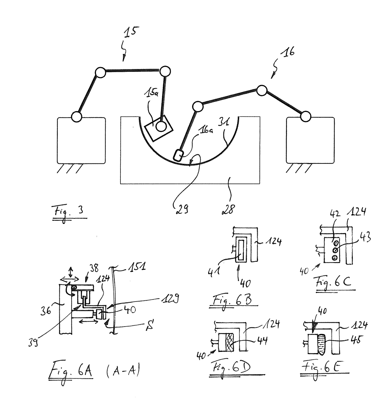
[0072]In a method which is shown schematically in FIG. 13, it is provided that the pre-assembly device 36 holds the elements 121-125 in a manner which is not completely rigid, but rather with a certain degree of free movability for compensating tolerances relative to one another and to the skin portion 151.

[0073]In a step S1, the skin portion 151 and the individual elements 121 to 125 are provided.

[0074]In a step S2, the elements 121 to 125 are arranged on the pre-assembly device 36 in such a way that said elements are held by means of the retaining devices 38.

[0075]In a step S3, the pre-assembly device 36 is taken, for example by means of a manipulation device 78, which can be for example a multi-axle robot (see FIG. 8), into the immediate vicinity of the skin portion 151. Some or all of the elements 121-125 in this case make contact with the skin portion 151 for connection, as a result of which the elements 121-125 automatically adjust in terms of the relative position and option...

second embodiment

[0080]A method is shown schematically in FIG. 14.

[0081]In a step S1′, the skin portion 151 and the individual elements 121 to 125 are provided.

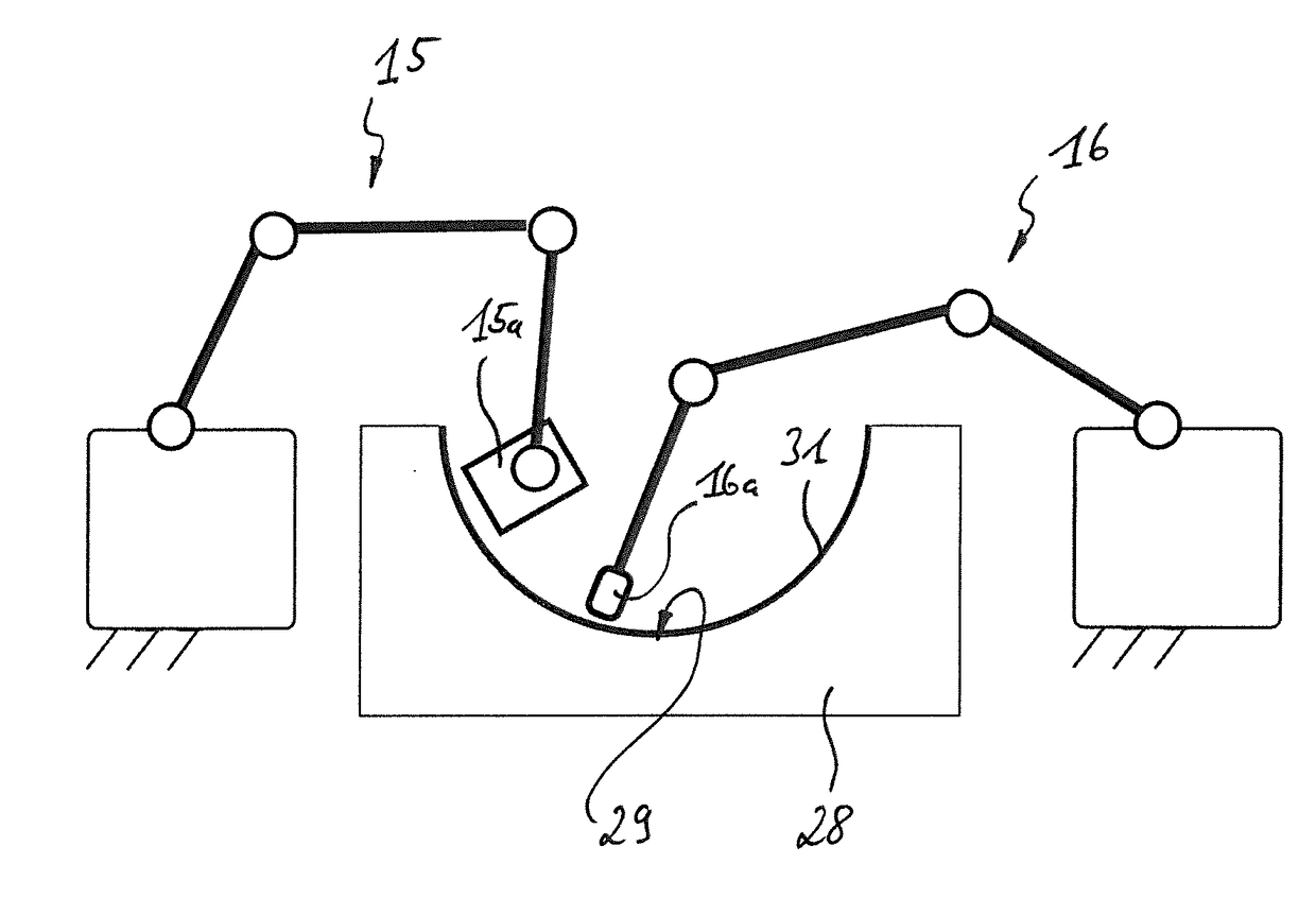
[0082]In a step S2′, as shown schematically in FIG. 7, the internal geometry of the skin portion 151 (what is known as the inner mould line or ILM), which remains in the female tool part 28 after the consolidation of the skin element 101 and during any assembly of additional components, is measured three-dimensionally, for example by means of an optical measuring means 115.

[0083]In a step S3′, the main frame 121 and the additional elements 122-125, namely the auxiliary frame 122, the intercostal elements 123 (intercostals) as well as the beam 124 and the ridge 125 (sills) are arranged on the pre-assembly device 36 and positioned and oriented by means of the retaining devices 38 with reference to the measurement data obtained from the three-dimensional measurement of the geometry of the skin portion 151.

[0084]After the completion of the step ...

third embodiment

[0089]FIG. 15 is a schematic view of a method according to a

[0090]In a step S1″, the skin portion 151 and the individual elements 121 to 125 are provided.

[0091]In a step S2″, as shown schematically in FIG. 7, the internal geometry of the skin portion 151, which remains in the female tool part 28 after the consolidation of the skin element 101 and during any assembly of additional components, is in turn measured three-dimensionally, for example by means of the optical measuring means 115.

[0092]In a step S3″, the main frame 121 is arranged on the pre-assembly device 36 and, by means of the retaining devices 38, using the measurement data obtained from the three-dimensional measurement of the geometry of the skin portion 151, is positioned and oriented in a precise manner.

[0093]In a step S4″, the additional elements 122-125, namely the auxiliary frame 122, the intercostal elements 123 (intercostals) as well as the beam 124 and the ridge 125 (sills) are arranged on the pre-assembly devi...


PUM

PropertyMeasurementUnit
Thermoplasticityaaaaaaaaaa

Abstract

A method for integrating a backing-structure assembly in a structure of an aircraft or spacecraft is described. In this case, a plurality of individual elements is joined to form the backing-structure assembly. The individual elements for the backing-structure assembly and a skin portion for the structure are provided. The elements are arranged on a pre-assembly device which comprises retaining devices, which are each configured to hold one of the elements so as to be adjustable with respect to the position and / or location thereof. Some or all of the elements are connected to the skin portion. In the method, by adjusting the retaining devices for tolerance compensation, gaps between joint regions of the elements and the skin portion are eliminated or adjusted.

Description

FIELD OF THE INVENTION[0001]The present invention relates to integrating a backing-structure assembly, in particular a door-surrounding structure, in a structure of an aircraft or spacecraft, for example of an aeroplane.[0002]Although the present invention can be applied to assemblies of various types, which can be used as part of or in backing structures of a structure of an aircraft or spacecraft, the present invention and the problem addressed thereby are to be described in greater detail below using the example of integrating a door-surrounding structure in an aeroplane structure.BACKGROUND OF THE INVENTION[0003]Door-surrounding structures are used in aeroplanes to reinforce and brace a fuselage skin in the region of a door cut-out which is introduced into the fuselage skin. When integrating a door-surrounding structure of this type in the structure of the aeroplane in a manner which is known to the applicant, the door-surrounding structure is composed of a multiplicity of indiv...

Claims


Application Information

Patent Timeline
IPC IPC(8): B29C65/00B29C65/04B29C70/38B29C65/08B29C70/34B29K71/00
CPCB29C66/721B29C70/345B29K2071/00B29C65/08B29C70/386B29C65/04B64F5/10B29C65/16B29C65/1612B29C65/42B29C66/80B29C66/90B64C1/12B29L2031/3076B64C1/068B29C65/18B29C65/26B29C65/305B29C65/36B29C66/0222B29C66/112B29C66/532B29C66/61B29C66/71B29C66/7212B29C66/81455B29C66/8362B29C66/863B29C65/02B29C66/72141B29L2031/3082B29C70/38B29C70/46B29K2307/04B29K2309/08Y02T50/40
Inventor JOERN, PAUL
Owner AIRBUS OPERATIONS GMBH
Learn More