Unmanned flying object, control method, and non-transitory recording medium storing program
a technology of unmanned flying objects and control methods, applied in vehicle position/course/altitude control, process and machine control, instruments, etc., can solve problems such as the capture of other objects in the air, such as suspicious unmanned flying objects
- Summary
- Abstract
- Description
- Claims
- Application Information
AI Technical Summary
Benefits of technology
Problems solved by technology
Method used
Image
Examples
first embodiment
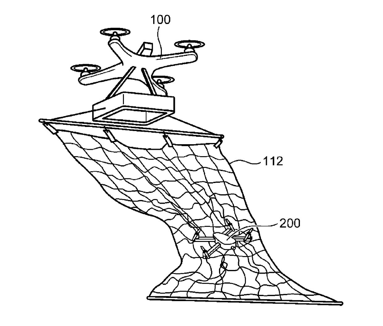
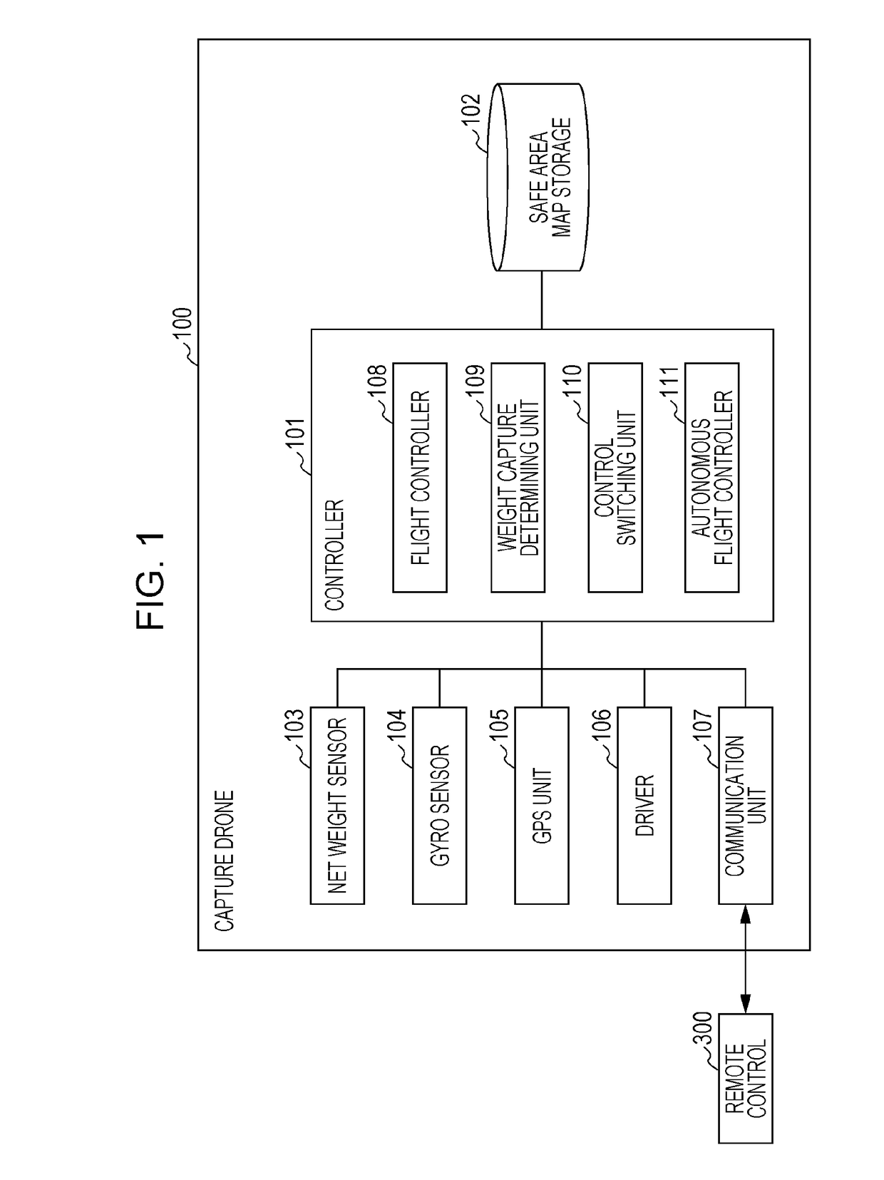
[0076]A capture drone being an example of an unmanned flying object according to this embodiment is described. FIG. 1 is a block diagram showing an exemplary configuration of a capture drone 100 according to a first embodiment of the present disclosure. The capture drone 100 shown in FIG. 1 is remotely operated by using a remote control (operation tool) 300. The capture drone 100 is an unmanned flying object capable of making autonomous flight. The capture drone 100 can make autonomous flight without receiving a remote instruction from the remote control 300.
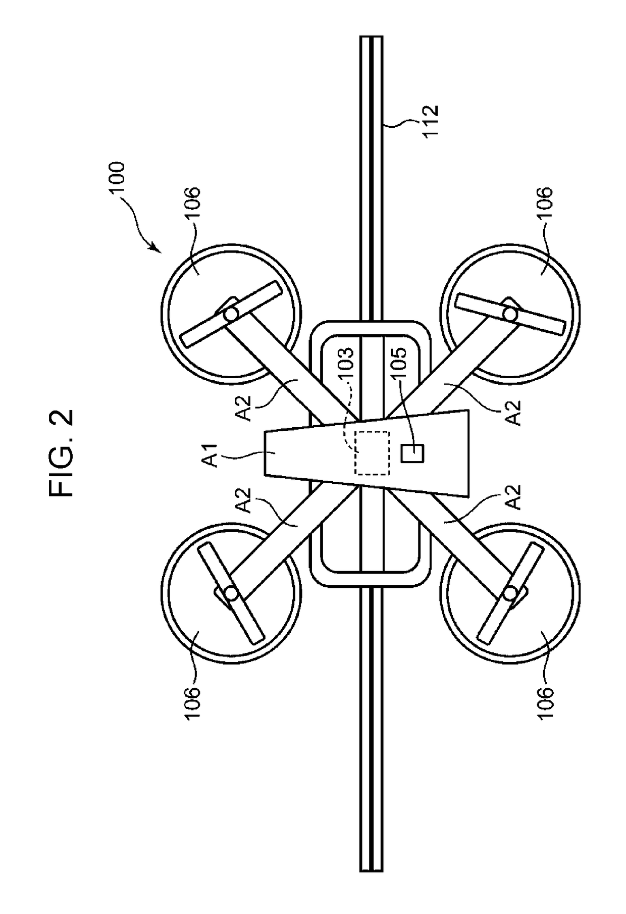
[0077]The capture drone 100 includes a controller 101, a safe area map storage102, a net weight sensor 103, a gyro sensor 104, a global positioning system (GPS) unit 105, a driver 106, and a communication unit 107. The controller 101 is formed of, for example, a processor, and includes a flight controller 108, a weight capture determining unit 109, a control switching unit 110, and an autonomous flight controller 111.
[0078]FIG. ...
first modification
[0127]An example of using a current sensor instead of the net weight sensor is described as a first modification of this embodiment. FIG. 12 is a block diagram showing an exemplary configuration of a capture drone 100a according to the first modification of the first embodiment of the present disclosure. FIG. 13 is an external view from an upper surface of the capture drone 100a shown in FIG. 12. To simplify illustration, four current sensors 113 shown in FIG. 13 are illustrated as a single current sensor 113 in FIG. 12.
[0128]The capture drone 100a shown in FIGS. 12 and 13 differs from the capture drone 100 shown in FIGS. 1 and 2 in that the current sensors 113 are provided instead of the net weight sensor 103, the controller 101 is changed to a controller 101a, and the weight capture determining unit 109 of the controller 101 is changed to a current capture determining unit 114 of the controller 101a. The other configuration of the capture drone 100a is similar to that of the captu...
second modification
[0137]An example of using a rotation speed sensor instead of the net weight sensor is described as a second modification of this embodiment. FIG. 15 is a block diagram showing an exemplary configuration of a capture drone 100b according to the second modification of the first embodiment of the present disclosure. FIG. 16 is an external view from an upper surface of the capture drone 100b shown in FIG. 15. To simplify illustration, four rotation speed sensors 115 shown in FIG. 16 are illustrated as a single rotation speed sensor 115 in FIG. 15.
[0138]The capture drone 100b shown in FIGS. 15 and 16 differs from the capture drone 100 shown in FIGS. 1 and 2 in that the rotation speed sensors 115 are provided instead of the net weight sensor 103, the controller 101 is changed to a controller 101b, and the weight capture determining unit 109 of the controller 101 is changed to a rotation speed capture determining unit 116 of the controller 101b. The other configuration of the capture drone...
PUM
 Abstract
Description
Claims
Application Information
 - R&D
- Intellectual Property
- Life Sciences
- Materials
- Tech Scout
- Unparalleled Data Quality
- Higher Quality Content
- 60% Fewer Hallucinations
Browse by: Latest US Patents, China's latest patents, Technical Efficacy Thesaurus, Application Domain, Technology Topic, Popular Technical Reports.
© 2025 PatSnap. All rights reserved.Legal|Privacy policy|Modern Slavery Act Transparency Statement|Sitemap|About US| Contact US: help@patsnap.com


