Rubber Tire Roller

a rubber tire roller and tire roller technology, applied in the direction of wheel guards, bumpers, ways, etc., can solve the problems of forming tunnels inside the machine frame, affecting the operation of the machine frame, so as to facilitate the operation and facilitate the access of the device. , the effect of convenient access

Active Publication Date: 2017-12-14
BOMAG
View PDF0 Cites 2 Cited by
  • Summary
  • Abstract
  • Description
  • Claims
  • Application Information

AI Technical Summary

Benefits of technology

[0020]This effect can be further enhanced by providing a step for an operator, in particular in the region of the viewing indentation configured to be open at the top. The step denotes, in particular, a platform or foothold on which the operator can place at least one foot or even two feet. In this case, the step is arranged at a certain distance from the ground on the machine frame so that the operator can reach the devices arranged vertically high up on the rubber tire roller a lot easier by climbing on the step. The step is particularly helpful wherever the viewing indentation configured to be open at the top is located. Together with the viewing indentation open at the top, the step makes it considerably easier to reach the devices of the rubber tire roller that are arranged high up.
[0021]Reaching devices arranged higher up on the rubber tire roller can be made still easier in a further embodiment by configuring a step recess in the machine frame in addition to the viewing indentation, in particular vertically above the step, said step recess preferably being configured in the viewing indentation. The step recess is also configured as an indentation in the machine frame and preferably extends from the vertically lower end of the rubber tire roller or from the step over the entire height of the rubber tire roller vertically upward. This embodiment can be realized in a particularly advantageous manner if the step recess, in particular in the vertically top region of the rubber tire roller, is combined with the viewing indentation, by which means a certain area of the viewing indentation or step recess is used both as a step for an operator as well as for the driver's view of the wheels. As a result of this dual use of one a...

Problems solved by technology

At the same time, the machine should be configured to be as compact as possible, which has led to the machine frame of generic rubber tire rollers typically being comparatively massive or bulky.
Said visual supports, however, get dirty comparatively quickly, while the driver of the rubber tire roller recognizes considerably fewer details regarding the position of the wheel edges or mate...

Method used


Image

  • Rubber Tire Roller
  • Rubber Tire Roller
  • Rubber Tire Roller

Examples


Embodiment Construction

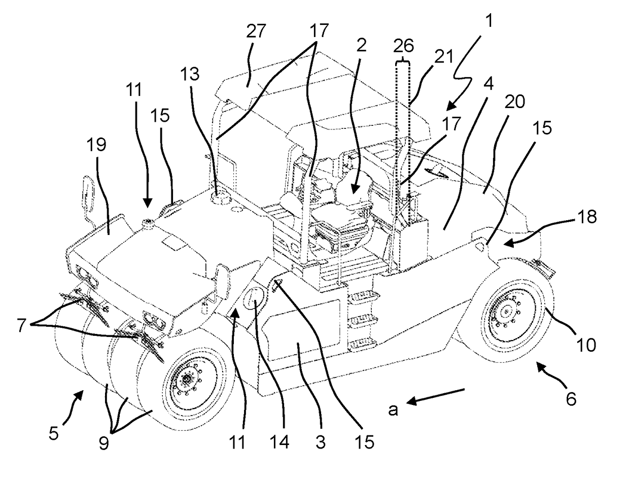
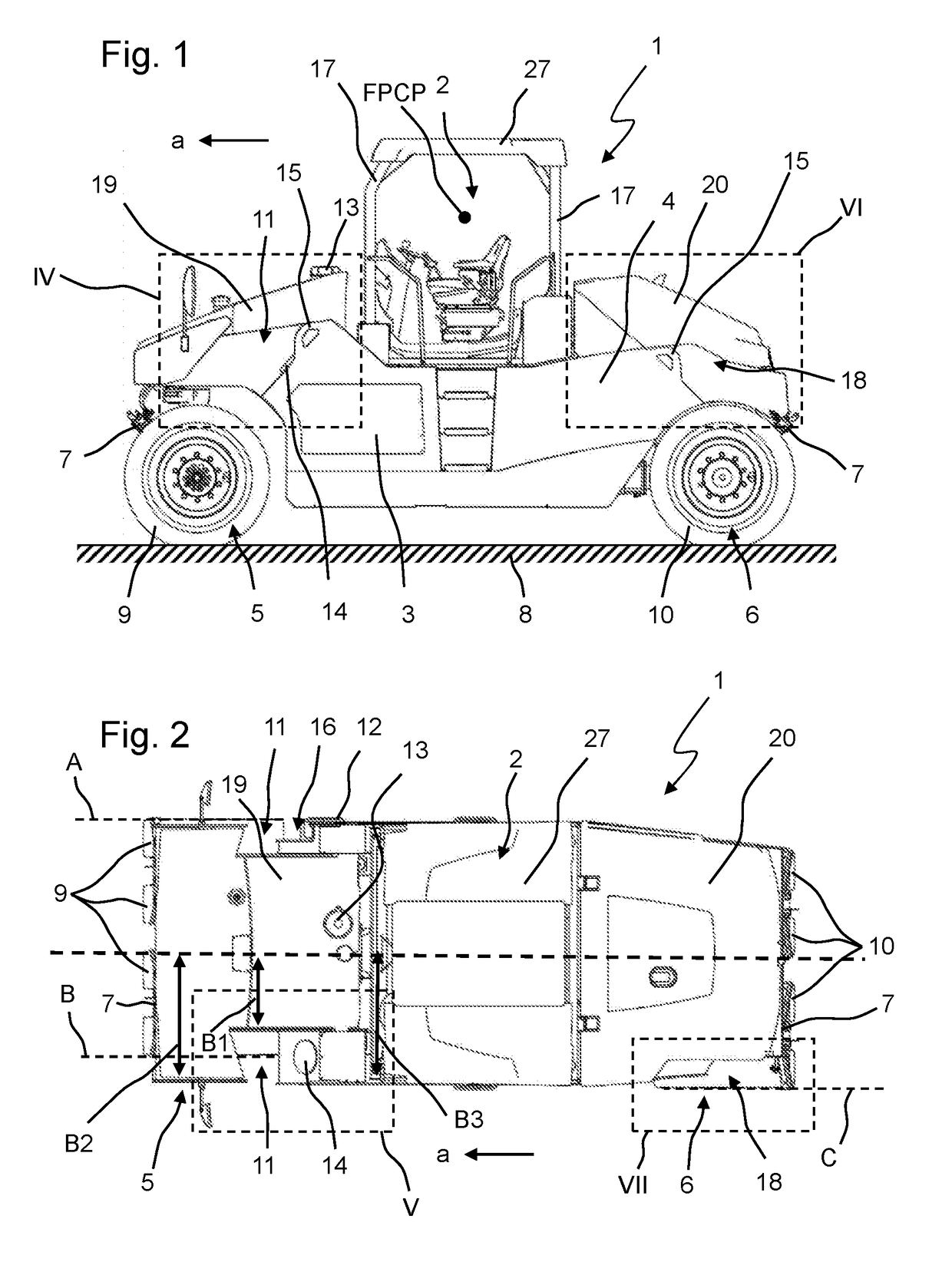
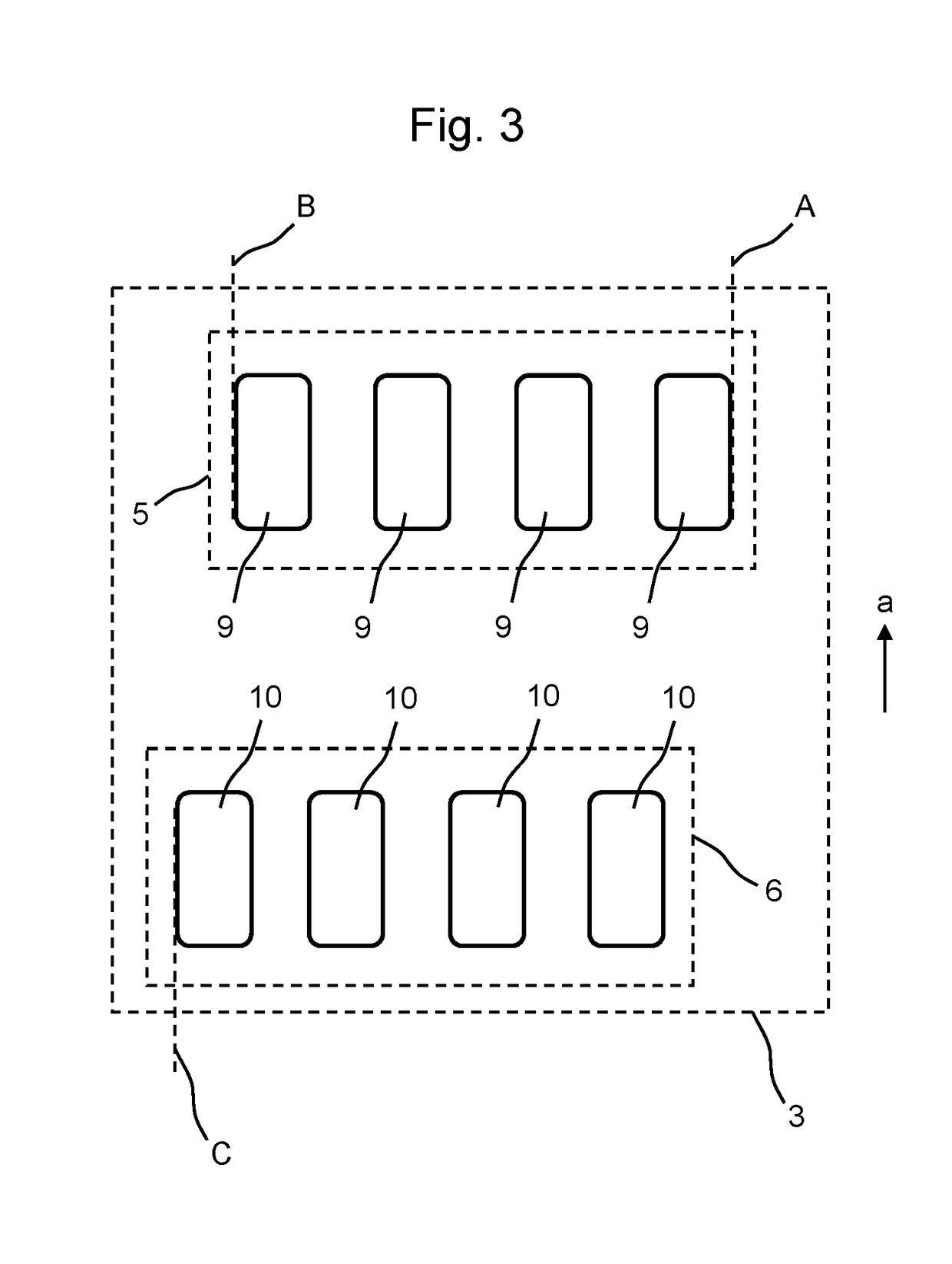
[0037]FIGS. 1 to 11 show a preferred illustrative embodiment of a rubber tire roller 1 according to the present invention. Generally, rubber tire rollers 1 comprise an operating platform 2 and a machine frame 3. During operation, the rubber tire rollers 1 are driven by a power source 4, mostly a diesel engine, and move alternately in the forward direction a or contrary to the forward direction a over the ground 8 by means of a driven front undercarriage 5 and a rear undercarriage 6. The undercarriages 5 and 6 respectively comprise four individual wheels arranged next to one another. Ideally, a driver's seat that is displaceable over the width of the platform is arranged on the operating platform 2. In FIG. 1, an approximate position of the FPCP in accordance with DIN ISO 5006:2017 is indicated for illustrative purposes.

[0038]In order to render the steering of the machine easier for the driver of the rubber tire roller 1, the embodiment of the rubber tire roller 1 shown comprises two...


PUM


Abstract

The present invention relates to a rubber tire roller for ground compaction, comprising a machine frame and an operating platform and front and rear undercarriages supporting the machine frame, wherein the undercarriages each comprise at least one wheel. A fundamental idea of the present invention lies in viewing indentations that are open to the side.

Description

CROSS-REFERENCE TO RELATED APPLICATION[0001]The present application claims priority under 35 U.S.C. §119 of German Patent Application No. 10 2016 007 170.2, filed Jun. 13, 2016, the disclosure of which is hereby incorporated herein by reference in its entirety.FIELD OF THE INVENTION[0002]The present invention relates to a rubber tire roller for ground compaction.BACKGROUND OF THE INVENTION[0003]A generic rubber tire roller is known, for example, from EP 0 864 964 A2. Rubber tire rollers are ground compaction machines equipped with wheels, usually rubber wheels, with which they drive over a ground to be compacted. To this end, generic rubber tire rollers comprise a machine frame with an operating platform and front and rear undercarriages supporting the machine frame, the undercarriages respectively comprising at least one wheel. The indications “front” and “rear” relate here to the forward direction of the rubber tire roller, the rubber tire roller normally being driven over the gro...

Claims


Application Information

Patent Timeline
IPC IPC(8): E01C19/23E02D3/032E01C5/08E01C19/30
CPCE01C19/236E01C19/233E01C19/30E01C5/085E02D3/032B60R19/03E01C19/238E01C19/26E01C19/27B60R2019/002
Inventor BERG, CHRISTIANEINOLF, ERNST-JOSEFHAUBRICH, THOMASKLEIN, THOMASSCHONBERG, TOBIAS
Owner BOMAG
Why Eureka
Try Eureka