Flow control devices in sw-sagd

a flow control device and sw-sagd technology, applied in the direction of fluid removal, sealing/packing, borehole/well accessories, etc., can solve the problems of increasing sand production and concomitant damag

Active Publication Date: 2017-12-14
CONOCOPHILLIPS CO
View PDF8 Cites 6 Cited by
  • Summary
  • Abstract
  • Description
  • Claims
  • Application Information

AI Technical Summary

Benefits of technology

[0026]Preferably, the method includes preheat cyclic steam phases, wherein steam is injected throughout both injector and producer segment, for e.g. 20-50 days, then allowed to soak into the reservoir, e.g., for 10-30 days, and this preheat phase is repeated two or prefe...

Problems solved by technology

One issue with any type of completion in a steam recovery process is steam flashing at the slots, ...

Method used


Image

  • Flow control devices in sw-sagd
  • Flow control devices in sw-sagd
  • Flow control devices in sw-sagd

Examples


Embodiment Construction

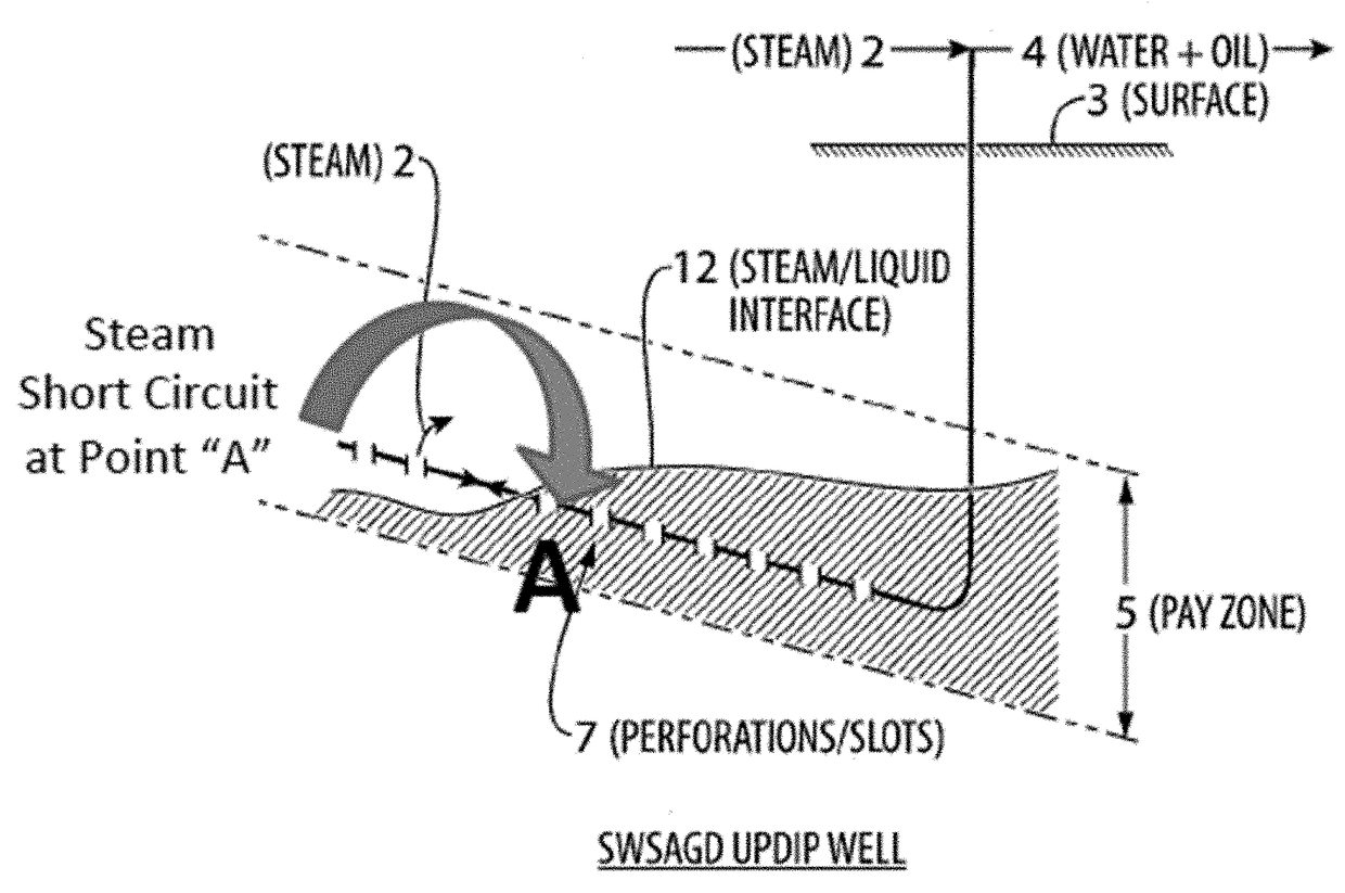
[0092]The present disclosure provides a novel well configurations and method for SW-SAGD, wherein passive or active inflow control devices are used together with packers prevent steam break through.

[0093]ICDs are placed at the end of the producer nearest the injector, thus reducing the problem of steam cycling at the toe. However, ICDs can also be placed in the injector portion, thus preventing steam loss even at the toe. Further, if flow control along the producer length is needed, e.g., due to uneven steam chamber development, it is advantageous to place ICDs along the length of the producer.

[0094]Use of ICDs all along the well serves to minimize breakthrough along its entire length, which is particularly beneficial in SW-SAGD since there is no vertical separation between steam injection and production. Thus, this placement is generally preferred.

[0095]Spacing of ICD's may be dictated by reservoir heterogeneity. However, it may also be possible to decrease the spacing of the ICDs ...


PUM


Abstract

The present disclosure relates to a particularly effective well configuration that can be used for single well steam assisted gravity drainage of SW-SAGD wherein steam flashing through production slots is prevented by included passive inflow control devices or active interval control valves in the completion.

Description

PRIORITY CLAIM[0001]This application is a non-provisional application which claims benefit under 35 U.S.C. §119(e) to U.S. Provisional Application Ser. No. 62 / 347,806 filed Jun. 9, 2016, entitled “FLOW CONTROL DEVICES IN SW-SAGD,” which is incorporated herein in its entirety.FEDERALLY SPONSORED RESEARCH STATEMENT[0002]Not Applicable.FIELD OF THE DISCLOSURE[0003]This disclosure relates generally to well configurations that can advantageously produce oil using steam-based mobilizing techniques. In particular, it relates to single well gravity drainage techniques wherein steam breakthrough is prevented using strategically placed inflow control devices.BACKGROUND OF THE DISCLOSURE[0004]Many countries in the world have large deposits of oil sands, including the United States, Russia, and the Middle East, but the world's largest deposits occur in Canada and Venezuela. Oil sands are a type of unconventional petroleum deposit, containing naturally occurring mixtures of sand, clay, water, an...

Claims


Application Information

Patent Timeline
IPC IPC(8): E21B43/12E21B43/24E21B34/06E21B33/12E21B34/16
CPCE21B43/121E21B43/2406E21B34/063E21B33/12E21B43/123E21B43/126E21B34/16E21B43/24E21B43/12E21B43/305E21B43/2408
Inventor WHEELER, THOMAS J.BROWN, DAVID A.
Owner CONOCOPHILLIPS CO
Why Eureka
Try Eureka